


186
Ladder Programming with Tag Data Links Section 6-3
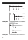
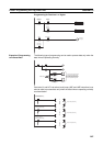
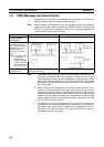
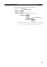
Note Even if an error occurs in communications with a target device, the input data
from the target device will remain stored in words allocated in memory to the
local node. To prevent malfunctions, write the ladder program so that input
data processing will not be performed when the Unit Error Occurred Flag
(word n+10 bit 00) is ON.
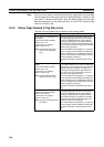
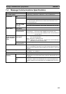
6-3-2 Status Flags Related to Tag Data Links
The status of the tag data links is reflected in the following words.
Name (allocated area) Contents
Target Node PLC Operating Flag
Information
Layout set to default settings:
Words n+2 to n+5
Layout set to user settings:
Words n+32 to n+47
Note Corresponds to the PLC
status’s PLC Operating
Flag.
Each flag indicates the operating status of the
corresponding target node PLC of connections
in which the EtherNet/IP Unit is the originator.
The flag corresponding to the target node’s tar-
get ID will be ON when the PLC Operating Flags
for all connections with that target node indicate
that the PLC is operating.
Each node address’s flag location (i.e., target ID)
can be changed from the Network Configurator.
The PLC status flags are enabled when the PLC
status is included in the communications data for
both the originator and target.
The data in this table is refreshed when neces-
sary.
Target Node PLC Error Flag Infor-
mation
Layout set to default settings:
Words n+6 to n+9
Layout set to user settings:
Words n+48 to n+63
Note Corresponds to the PLC
status’s PLC Error Flag.
Each flag indicates the error status (logical OR
of non-fatal and fatal errors) of the corresponding
target node PLC of connections in which the Eth-
erNet/IP Unit is the originator. The flag corre-
sponding to the target node’s target ID will be
ON if even one error is indicated in any of the
connections with that target node.
Each node address’s flag location (i.e., target ID)
can be changed from the Network Configurator.
The PLC status flags are enabled when the PLC
status is included in the communications data for
both the originator and target.
The data in this table is refreshed when neces-
sary.
Normal Target Node Flag Table
Layout set to default settings:
Words n+20 to n+23
Layout set to user settings:
Words n+16 to n+31
Note Does not correspond to the
PLC status.
Each flag indicates the connection status of the
corresponding target node PLC of connections
in which the EtherNet/IP Unit is the originator.
The flag corresponding to the target node’s tar-
get ID will be ON when connections are estab-
lished for all connections with that target node
indicate that the PLC is operating.
Each node address’s flag location (i.e., target ID)
can be changed from the Network Configurator.
The data in this table is refreshed when neces-
sary.