


351
Using the LED Indicators and Display for Troubleshooting Section 14-2
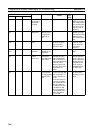
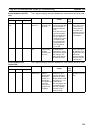
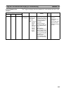
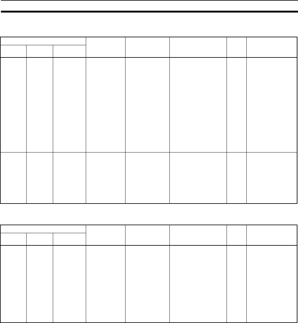
Errors Related to the CPU
Unit
The 7-segment display alternates between the node address and error code.
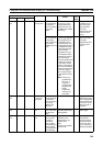
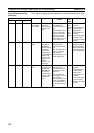
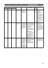
Errors Related to the
Control Bits
The 7-segment display alternates between the node address and error code.
Indicator Error Cause Unit operation (Flag
status)
Error
log
(hex)
Countermeasure
MS NS 7-segment
Flashing
red
--- HH CPU Unit
Fatal Error
A fatal error
occurred in the
CPU Unit.
• If the Unit is the orig-
inator of the tag data
link connection, it
stops communica-
tions.
• If the Unit is the tar-
get of the tag data
link connection and
the PLC status is
included in the com-
munications data,
the corresponding
Target Node PLC
Error Flag will be
turned ON.
0015 Eliminate the
cause of the error
in the CPU Unit.
The tag data link
will restart auto-
matically when the
cause of the error
is eliminated.
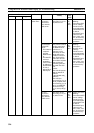
--- --- --- Output OFF
Error
An Output OFF
(output inhibit)
condition
occurred in the
CPU Unit.
The tag data link’s
send data will be
cleared to 0 in accor-
dance with the Output
OFF settings, and
data transfer will con-
tinue with that data.
--- Turn OFF the CPU
Unit’s Output OFF
Bit (A50015). The
tag data link’s send
data will be
restored automati-
cally when this bit
is turned OFF.
Indicator Error Cause Unit operation (Flag
status)
Error
log
(hex)
Countermeasure
MS NS 7-segment
--- --- C6 Multiple
Switches ON
Two or more
software
switches were
ON simulta-
neously, or a
second soft-
ware switch was
turned ON
before a prior
operation was
completed.
The error code will be
displayed on the 7-
segment display for
30 seconds, and the
Multiple Switches ON
Error Flag (n+11, bit
14) will go ON.
The error display will
be cleared the next
time that a settings
operation is com-
pleted normally.
--- Execute control bit
operations one at a
time.