


221
Communicating between OMRON PLCs Section 8-6
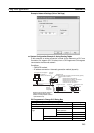
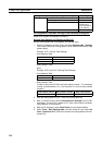
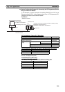
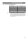
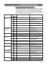
8-6-2 PLC Communications Data Areas
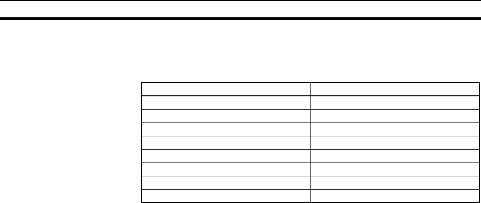
The following table shows the I/O data areas involved when SEND(090) and
RECV(098) are used.
Note 1. Data cannot be written to words A000 to A447 in the Auxiliary Area.
2. A maximum of 13 banks in the EM Area can be used for a CS1/CJ1 CPU
Unit. A maximum of 25 banks in the EM Area can be used for a CJ2H CPU
Unit. A maximum of 4 banks in the EM Area can be used for a CJ2M CPU
Unit. For details regarding the EM Area, refer to the operation manual for
the PLC that is used. Refer to the operation manual for your CPU Unit to
confirm EM Area support.
Area Range
CIO Area CIO 0000 to CIO 6143
Work Area W000 to W511
Holding Area H000 to H1535
Auxiliary Area A000 to A959 (See note 1.)
Timer Area TIM0000 to 4095
Counter Area CNT0000 to 4095
DM Area D00000 to D32767
EM Area E00000 to E32767 (See note 2.)