


258
Receiving Explicit Messages Section 9-2
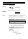
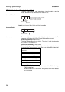
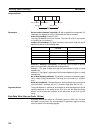
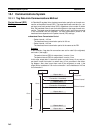
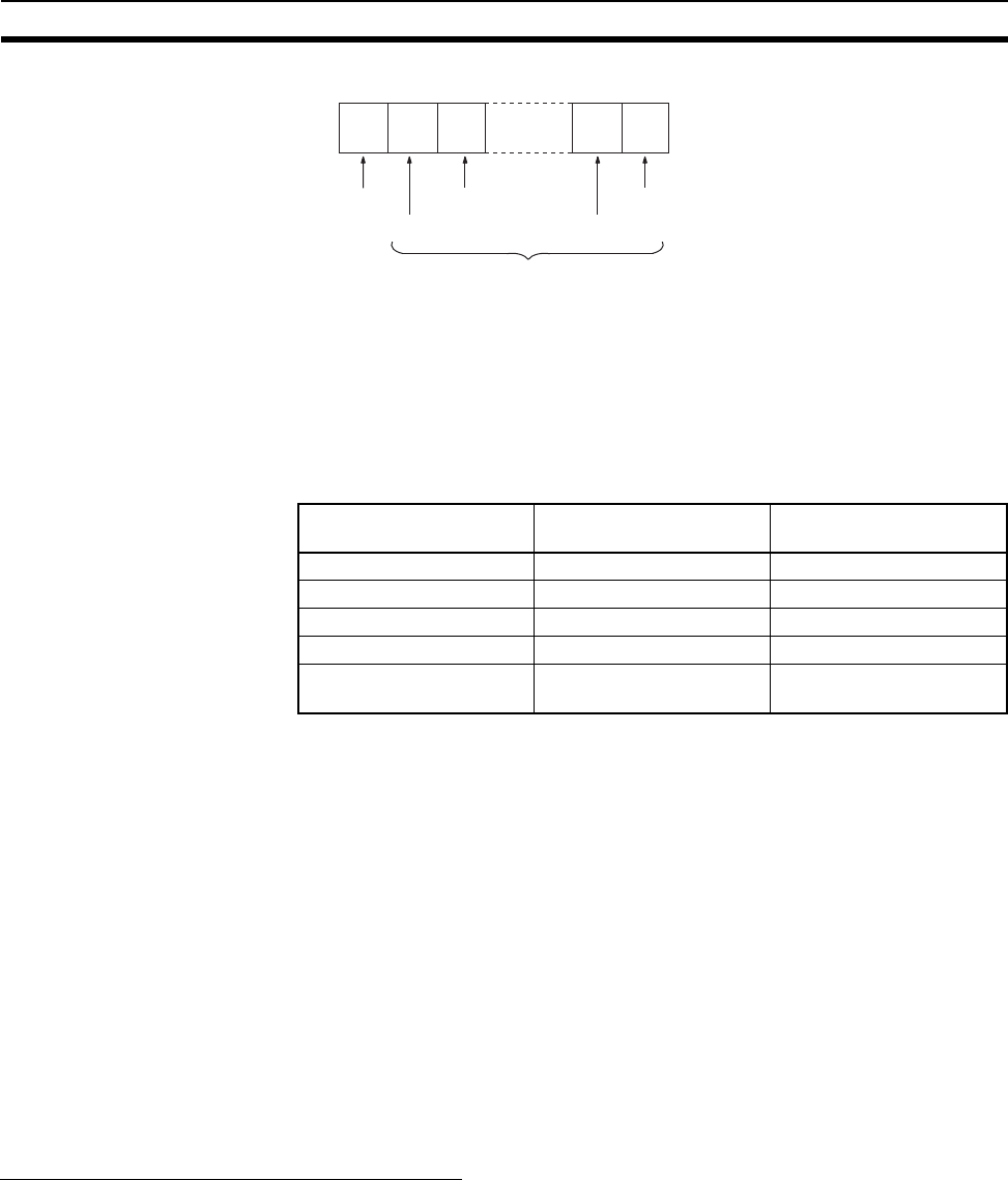
Response Block
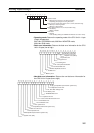
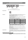
Parameters Service code (command, response): ID Hex is specified for commands. For
responses, the highest bit will turn ON and 9D Hex will be returned.
Class ID (command): Always C4 (2F).
The class ID depends on the unit version. The class ID is C4 for unit version
2.0, and 2F for unit version 1.0.
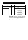
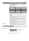
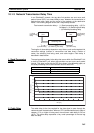
Instance ID (command): The type of memory area that will read the data is
specified as shown in the following table.
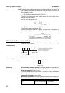
Address L, Address H (command): The address of the first word to read the
data from is specified in hexadecimal as shown below.
Address L: The lower 2 digits when the first word address is given in 4-digit
hexadecimal.
Address H: The higher 2 digits when the first word address is given in 4-digit
hexadecimal.
No of Read Words (command): The number of words of read data is speci-
fied in 1-byte (2-digit) hexadecimal. The range is 01 to 64 Hex (1 to 100 deci-
mal).
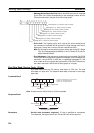
Read data (response): The specified area, word, and byte data is returned in
order from word L (low byte: bits 0 to 7) to word H (high byte: bits 8 to 15).
Important Points The actual address L, address H, and number of write data bytes that can be
specified depends on the model of the CPU Unit, and the data area being
written. Do not exceed the boundary of the data areas for the PLC you are
using.
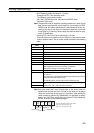
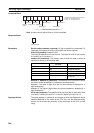
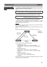
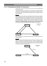
Byte Data Write (Service Code: 1E Hex)
Byte Data Write writes data to an I/O memory area in a CPU Unit. The write
word data is in byte units. The command block is specified in high-to-low byte
order, as shown in the following diagram.
9D
Service Code
Word data L
Word data H
Word data L
Word data H
Read data (200 b
y
tes max.)
Instance ID (Hex) CPU Unit memory area
for read
Word range
01 CIO 0000 to 6143
03 DM D00000 to D32767
04 WR W000 to W511
05 HR H000 to H1535
08 to 20 EM, banks 0 to 18 En_00000 to En_32767
(n: 0 to 18)