


Appendix C - IR-ETH Interface Module HCD-E1 Installation & Operation Manual
C-2 Technical Specifications
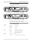
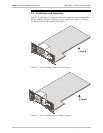
C.2 IR-ETH Connector Options
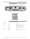
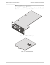
Figure C-2 and Figure C-3 show the rear panel of HCD-E1 with the IR-ETH
connector options.
ALM RLY
TX IN
SUB E1
RX OUT
NETWORK
LINE A
12
HDSL
LINE B
4
5
P
O
W
E
R
CHANNEL
CH.1
CH.2
10BASE-T
TX
RX
COLL
LINK
CH.1
~100-240 VAC
0.5A T 250V
Figure C-2 HCD-E1 Rear Panel for the 10BaseT Option
10BASE-T
RX
COLL
TX
ALM RLY
TX IN
SUB E1
RX OUT
NETWORK
LINE A
12
HDSL
LINE B
4
5
P
O
W
E
R
CHANNEL
CH.1
CH.2
CH.1
~100-240 VAC
0.5A T 250V
Figure C-3 HCD-E1 Rear Panel for the 10Base2 Option
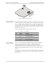
To connect the external equipment to the Ethernet interface, use standard
Ethernet cables with RJ-45 or BNC connector, respectively.
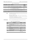
C.3 Technical Specifications
General
LAN Table
10,000 addresses
Filtering and
Forwarding
15,000 pps
Buffer
256 frames
Delay
1 frame
LAN
Standard
Conforms to IEEE 802.3/Ethernet
Data Rate
10 Mbps (20 Mbps 10BaseT FDX)
Connectors
10BaseT (UTP): Shielded RJ-45
10Base2: BNC connector
WAN
Protocol (internal)
HDLC
Data Rate
According to the modem transmission rate