HCD-E1 Installation & Operation Manual Chapter 1 - Introduction
01/01/01 08:07 Functional Description 1-5
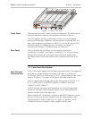
Figure 1-2 HCD-E1 3D View
Front Panel
The front panel provides control over the unit operation. The LEDs provide
real-time indications related to the operation and status of the unit.
The LCD together with three push-button switches are used to display
status (alarm) messages, diagnostics and performance monitoring data, test
status and configuration parameters of HCD-E1. You can also use the LCD
and push buttons to configure the unit. For details, see Chapter 3,
Operation and Chapter 5, Troubleshooting and Diagnostics.
Rear Panel
The rear panel of the unit allows access to interface and power
connections. For details, see Chapter 2, Installation. For versions with the
Ethernet data channel, the rear panel contains Ethernet module LEDs
providing real-time indications related to the operation and status of the
LAN.
1.3 Functional Description
Data Channel
Characteristics
HCD-E1 data ports support user-selectable transmission rates. The supported
data rates are integer multiples of 56 kbps or 64 kbps (n × 56 kbps or
n × 64 kbps, where n is in the range of 1 to 32, corresponding to rates in the
range of 56 kbps to 1792 kbps, or 64 kbps to 2048 kbps respectively).
HCD-E1 supports the following types of data port interfaces: RS-530, V.35,
X.21, V.36/R-449/422 and IR-ETH (10BaseT or 10Base2), IR-ETH/Q
(10BaseT) or IR-IP (10BaseT).
HCD-E1 has two data ports, each terminated in a 25-pin D-type female
connector. The units with an Ethernet interface arrive with the Ethernet
interface module built in the upper port.
When using the RS-530 interface, equipment with RS-530 interface can be
directly connected to the data channel connector using standard cables.
Equipment with V.36/RS-422/RS-449, X.21 and V.35 interfaces can be
connected by means of adapter cables, supplied with the unit.


