Chapter 2 - Installation and Setup HCD-E1
Installation & Operation Manual
2-2 Installation and Setup 11/12/00 10:36
2.2 Package Contents
The HCD-E1 package includes the following items:
•
HCD-E1 unit
•
HCD-E1 Installation and Operation Manual
•
AC power cord or DC power supply connector kit.
•
Interface adapter cable/s (interface ordering options, see Connecting the
Interfaces later in this chapter).
2.3 Installation and Setup
HCD-E1 is a standalone device designed for tabletop or bench installation. It
is delivered completely assembled. No provision is made for bolting the unit
to the tabletop.
To complete the installation of HCD-E1, you must perform the following (in
the given order):
•
Determine the required configuration of HCD-E1, according to your
application, and set the internal jumpers and switches accordingly.
•
Connect the E1 sublink, the HDSL lines, the data channels and the
control port, if necessary.
•
Connect power to the unit.
These procedures are described on the following pages.
Setting the
Internal Jumpers
and Switches
This section provides information on the functions of the internal jumpers
and switches, to help you in the selection of the correct setting for particular
application, and gives step-by-step instructions for performing the internal
settings. The default settings are also listed.
All the other configuration actions can be performed from the front panel or
from a control terminal, after the installation is completed. Information and
detailed instructions for these operations appear in Chapter 3 and
Chapter 4, respectively.
HCD-E1 Printed Circuit Boards
HCD-E1 comprises three printed circuit boards (PCBs): the main board and
two interface PCBs.
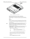
Figure 2-1 shows the location and identification of the boards installed in the
HCD-E1 unit.


