Chapter 1 - Introduction HCD-E1
Installation & Operation Manual
1-18 Functional Description 01/01/01 08:07
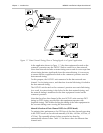
− Bit 3 - this bit is used as a Remote Alarm Indication (RAI), to notify the
equipment at the other end that the local equipment lost frame
alignment, or does not receive an input signal.
− The other bits, identified as S
a4
through S
a8
, are designated national
bits, and are actually available to the users, provided agreement is
reached as to their use. RAD equipment with SNMP agents can use
the S
a4
bit for in-band management traffic. The total data rate of the
in-band management traffic when using the S
a4
bit, is 4 kbps.
Multiframes
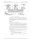
To increase the information carrying capacity without wasting bandwidth,
the frames are organized in larger patterns, called multiframes. Two types of
multiframes are generally used:
•
G732N, which consists of 2 frames (one odd frame and one even frame).
The G732N multiframe is generally used when time slot 16 is available to
the user. In this mode, the maximum number of time slots available for
payload is 31 (maximum payload data rate of 1984 Kbps). For systems
which use the Common-Channel Signaling (CCS) method, the CCS
information is often transmitted in time slot 16.
•
• •
•
G732S, which consists of 16 frames. The G732S multiframe is generally
used when time slot 16 serves for the transmission of end-to-end
signaling using Channel-Associated Signaling (CAS). CAS is typically used
on links that transfer voice channels. In this mode, the maximum number
of time slots available for payload is 30 (maximum data rate of
1920 kbps).
E1 Line Statistics Using CRC-4 Error Detection
HCD-E1 supports the CRC-4 function in accordance with ITU G.704, which
allows the evaluation of the quality of transmission over E1 links.
When the CRC-4 option is enabled, frames are arbitrarily grouped in groups
of 16 (these groups are called CRC-4 multiframes, and do not bear any
relationship to the 16-frame multiframe structures used with the G732S
super-frame explained above). A CRC-4 multiframe always starts with a
frame that carries the frame alignment signal. The CRC-4 multiframe
structure is identified by a six-bit CRC-4 multiframe alignment signal,
which is multiplexed into bit 1 of time slot 0 of each odd-numbered (1, 3, 5,
etc.) frame of the multiframe (up to frame 11 of the CRC-4 multiframe).
Each CRC-4 multiframe is divided into two submultiframes of 8 frames
(2048 bits) each. The detection of errors is achieved by calculating a four-bit
checksum on each 2048-bit block (submultiframe). The four checksum bits
calculated on a given submultiframe are multiplexed, bit by bit, in bit 1 of
time slot 0 of each even-numbered frame of the next submultiframe.


