


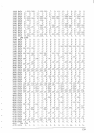
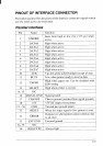
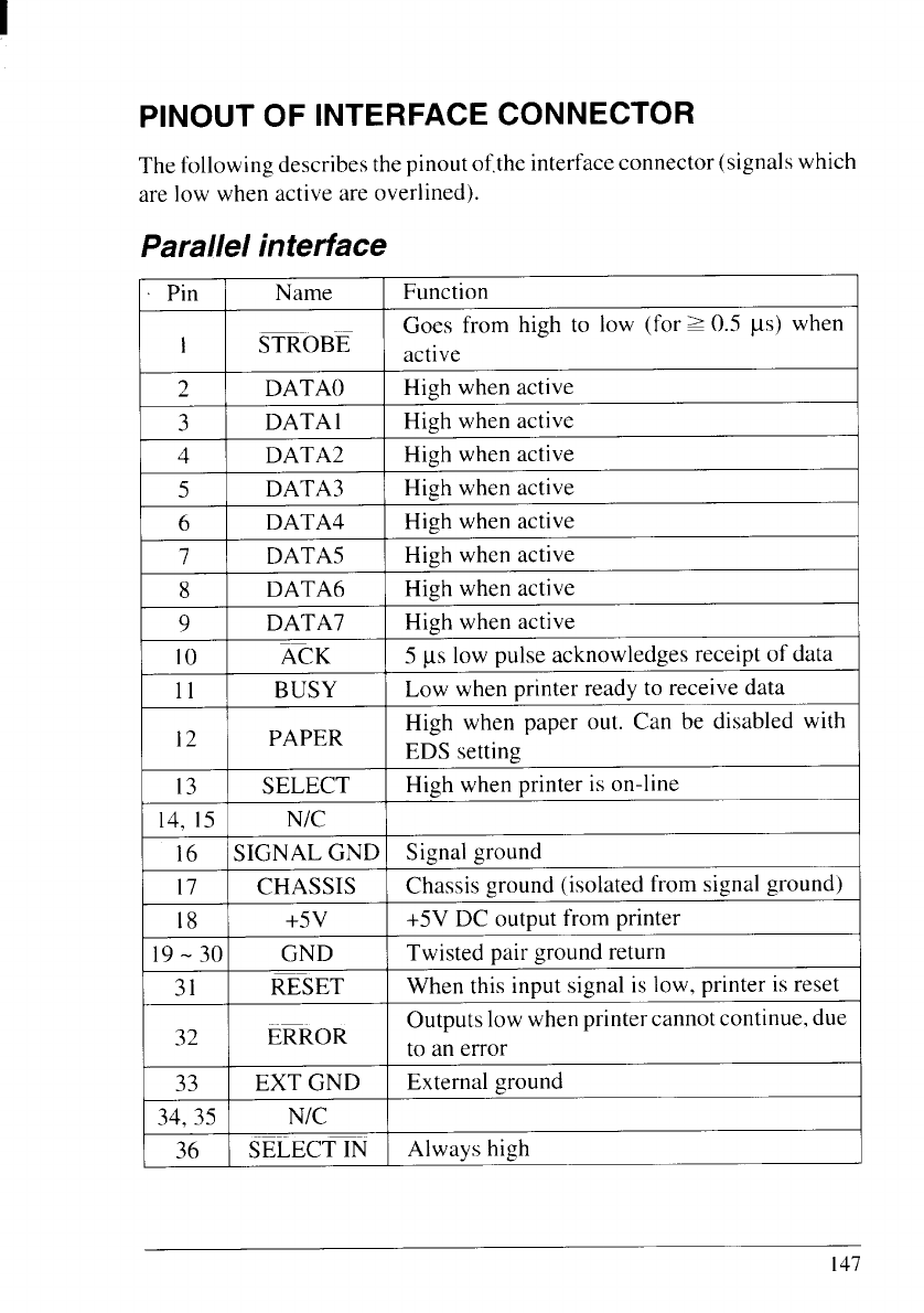
PINOUT OF INTERFACE CONNECTOR
The following describes thepinoutof,theinterface connector (signalswhich
are low when active are overlined).
Parallel interface
Pin Name
Function
Goes from high to low (for= 0.5 ps) when
1 STROBE
active
2 DATA()
High when active
3
DATA1
High when active
4 DATA2
High when active
5
DATA3
High when active
6
DATA4 High when active
7 DATA5
High when active
8
DATA6
High when active
9
DATA7
High when active
10 ACK 5 ps low pulse acknowledges receipt of data
11 BUSY
Low when printer ready to receive data
12 PAPER
High when paper out. Can be disabled with
EDS setting
13 SELECT
High when printer is on-line
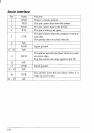
14, 15
N/C
16 SIGNAL GND Signal ground
17 CHASSIS Chassis ground (isolated from signal ground)
18
+5V
+5V DC output from printer
19-30 GND
Twisted pair ground return
31
RESET
When this input signal is low, printer is reset
32
Outputs low whenprinter cannot continue, due
ERROR
to an error
33
EXT GND External ground
34,35
N/C
36
SELECT IN
Always high
147