6 Sun Fire 280R Server Owner’s Guide • January 2001
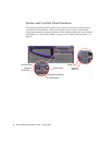
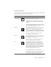
The system’s Power button is beside the keyswitch and is controlled by the
keyswitch settings. For more information about the keyswitch positions, see
“Keyswitch Settings” on page 9.
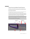
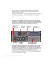
The system’s standard front panel and controls are illustrated in the figure below. An
optional tape drive is available in place of the DVD-ROM. For more information
about using the DVD-ROM drive, or the optional tape drive (if installed), see
Chapter 5.
For more information about status panel controls and indicators, see “Status and
Control Panel Features” on page 8.
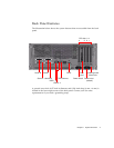
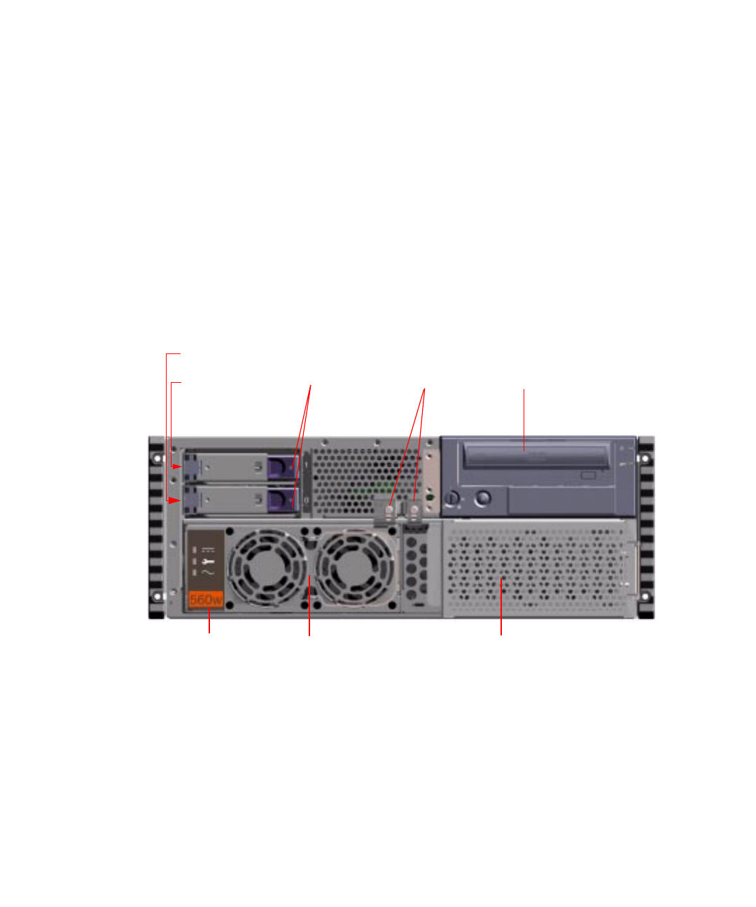
Opening the system’s front doors provides access to the system’s hot-pluggable
internal disk drives. Releasing the power supply retainers affords qualified service
personnel access to the hot-swappable power supplies. The illustration below shows
the additional accessible features when the system front doors are open.
Systems may be configured with one or two power supplies, and one or two disk
drives either of which is accessible when the system front doors are open. Each
power supply has an LED that displays the AC power, DC power, and fault status of
the supply. Only qualified service providers should access the power supplies. See
“Power Supply Failure” on page 195 for operational details of the LEDs.
Each disk drive has an LED indicating when lit steadily that the drive is present, and
if the LED is blinking that there is activity on the disk. For additional information
see “About Power Supplies” on page 95.
Power supply
retainers
Internal disk
drive LEDs
Internal drive 0
Internal drive 1
(option)
(default)
DVD-ROM or
optional tape drive
(power supply 2 optional)
Power supply
Power supply 2 filler panel
(default)
Power supply 1
LED display


