Basic Measurements
1760 Series Component Waveform/Vector Monitor User Manual
4-17
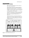
For better viewing of Light ning displays, the GAIN menu and
X5 can be selected. Press
CLEAR MENU to clear the GAIN
menu readout. Since the graticule is electronically gener-
ated, the calibration is not altered by X5 gain. Use the Verti-
cal Position control to view the entire display. When X5 gain
is no longer desired, select the
GAIN menu again, and set gain
to X1. To exit, push
GAIN menu again, or push CLEAR MENU.
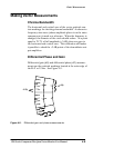
Amplitude Measurements
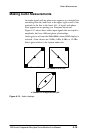
With color-difference formats, luminance increases from the
bright dot in the center of the graticule; it plots upward in the
upper half of the screen, and downward in the lower half.
The color-difference or chroma amplitude is the horizontal
deflection away from the luminance axis. A purely mono-
chrome signal is indicated by a vertical line along the lumi-
nance axis. Check that the signal appears within the targets
of the electronic graticule. If it is too close to the center dot,
it is too small; too far away, it is too large.
Encoder
Accuracy
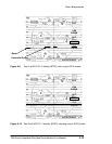
The Lightning display allows the operator to check encoder
accuracy by viewing the relative amplitudes of luminance
and color difference signals in one display.
T
iming
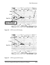
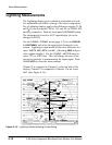
Lightning can also be used for evaluating interchannel tim-
ing. One input signal used for this display is a color bar that
is compatible with the Lightning graticule. Note the row of
graticule dots between the Green and Magenta boxes in both
the upper and lower halves of the Lightning display. If the
signal trace passes through the center dot of this row in each
half of the display, the interchannel timing is correct.
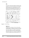
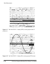
The modulated sin
2
pulse can also be used to check for tim-
ing errors using the Lightning display. When inter-channel
timing is correct, a straight line is seen. An ellipse indicates
a timing error. Due to lower bandwidth amplifiers this signal
has less noise obstructing the display than the Bowtie method


