Basic Measurements
1760 Series Component Waveform/Vector Monitor User Manual
4-21
Using the Bowtie Display
When used with the Bowtie signal, the Bowtie display is a
high-resolution timing indicator.
Route a Bowtie test signal from the generator, through the
equipment under test, and connect to the 1760--Series rear-
panel CH-A1, A2, and A3 connectors. Use caution when
deciding where the Bowtie signal is routed; when transcoded
to GBR or encoded to composite, it produces and illegal sig-
nal with potential unwanted side effects.
For a Bowtie display, push the 1760--Series front-panel
BOW-
TIE
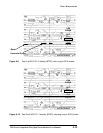
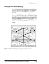
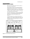
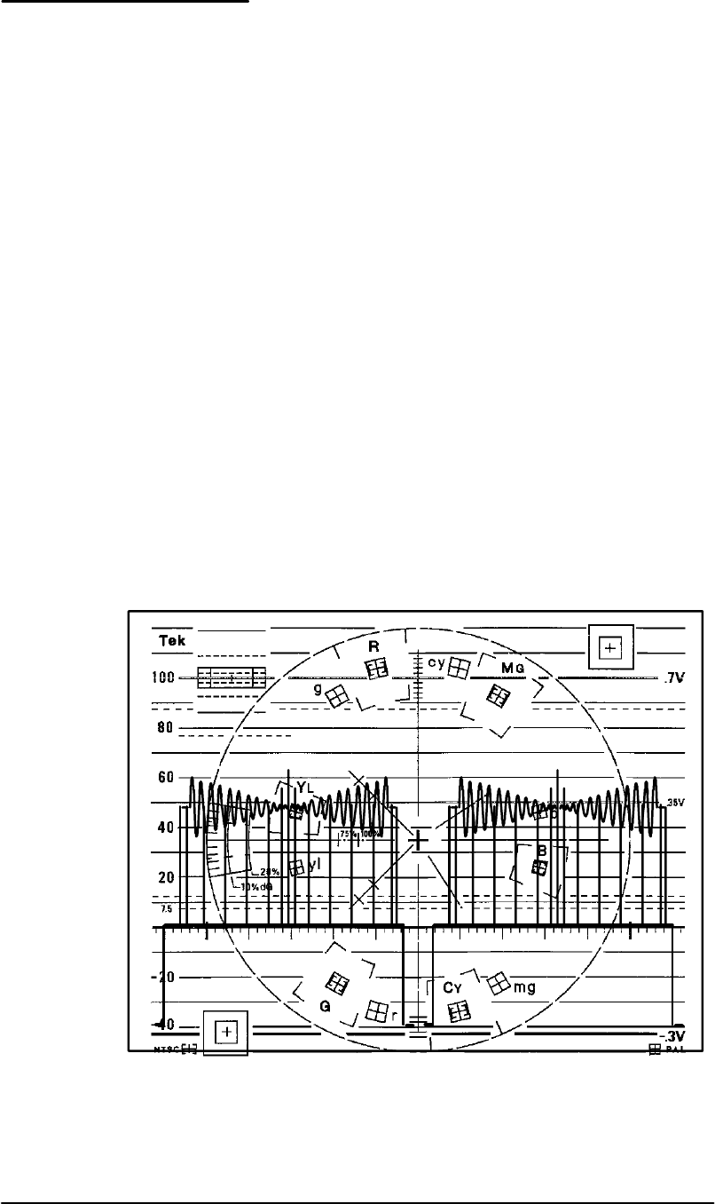
button. A two-line displa y of component signals will be
present: line one (left half of display) shows CH-1 minus
CH-2 and line two shows CH-1 m inus CH-3. See
Figure 4-17.
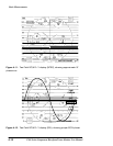
If the bowtie patterns have a sharp null, and the null is lo-
cated in the center of each line, both timing and relative am-
plitudes are correct. Relative amplitude errors will decrease
the depth of the null. Interchannel timing errors will move
the position of the null.
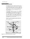
Figure 4-17. Bowtie display showing a sharp null.


