Appendix C: User Service
1760 Series Component Waveform/Vector Monitor User Manual
C-5
CAUTION
A 2% RMA flux content solder is recommended for
making repairs in this instrument. Cleaning of
rosin residue is not recommended. Most cleaning
solvents tend to reactivate the rosin and spread it
under components where it may cause corrosion
under humid conditions. The rosin residue, if left
alone, does not exhibit these corrosive properties.
Replacing the CRT Filter
A smoke-gray filter is installed over the face of the CRT.
The filter part number is given on page 1-7. If the filter be-
comes damaged, it can be replaced in the following manner:
1. Remove the five knobs below the CRT.
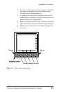
2. Insert a small, straight-blade screwdriver into the re-
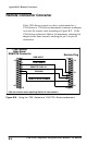
cessed area on either the right or left side of the panel.
Pry gently until the panel snaps out of the front-panel
frame. See Figure C-1 for panel and recess location.
3. Remove the two Torx screws that fasten the bezel to
the instrument.
4. Grasping the bottom of the bezel, pull out and upward to
remove the bezel from the instrument. (There are two
hinges at the top of the bezel that hold it in place; once
the bezel is at an approximate 45° angle with the front
panel, they will disengage.)
5. Remove the damaged filter and snap the new filter into
place on the back side of the bezel. Position the ridged
side of the filter towards the CRT to eliminate unwanted
visual effects on the CRT face.
6. Replace the bezel and bezel screws. Tighten screws (8
in lbs).


