Functional Overview
1760 Series Component Waveform/Vector Monitor User Manual
3-5
Displaying a Signal
Inputs
There are eight rear-panel loop-through inputs, which may
eliminate the need for an external routing switcher. The in-
puts can be displayed singly or in combination.
Without
PARADE or OVERLAY selected, only one i nput selec-
tion can be made at a time. Each input channel button (in-
cluding
A123 / B123) toggles between A and B, and is
cancelled when another input button is pressed.
With
PARADE or OVERLAY selected, the input channels can be
displayed in combination. Pushing an input channel button
sequences through the labeled channels, both, then off. Push-
ing another input button does not cancel the current selec-
tion, but adds to it. To return to “single input” operation,
push the
PARADE/OVERLAY button until it is off (LED is no
longer lighted).
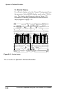
A123 / B123
Selecting A123 provides a side-by-side display of the CH-A1,
CH-A2,
and CH-A3 inputs (B123 displays the CH-B1, CH-B2, and
CH-B3 inputs). This is designed for monitoring component
signals.
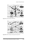
Parade
Selecting PARADE displays the input channels l ast selected
for
PARADE, allowing a custom configurati on of inputs. In
PARADE mode , the LINE/FIELD button offers only t wo choic es:
one line and one field.
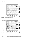
PARADE allows up to four channels to be displayed side-by-
side. Additional channels will be overlaid.


