www.ti.com
525
2
1
4
3
6
5
19
Field1active
Field1image
20
21
22
23
262
263
264
265
266
267
268
269
282
Field2active
283
284
285
286
Field2image
524
525
1
Field1blanking
1
2
1
2
239
240
240
240
240
240
240
240
240
240
240
240
240
240
240
239
240
240
240
240
240
240
240
240
240
240
240
240
ILCOUNTFLCOUNT
FLD
VBLNK
A
VSYNC
A
Active
horizontal
output
FIFOdata
FIFOdata
Defaultvalue
Defaultvalue
FIFOdata
FIFOdata
FIFOdata
FIFOdata
FIFOdata
FIFOdata
IMGVOFF1=2
IMGVSIZE1=240
IMGVOFF2=3
IMGVSIZE2=240
FRMHEIGHT =525
VBITSET1=n/a
VBITCLR1=n/a
VBITSET2=n/a
VBITCLR2=n/a
VBLNKXSTART1=720
VBLNKYSTART1=1
VBLNKXSTOP1-720
VBLNKYSTOP1-21
VBLNKXSTAR2=360
VBLNKYSTART2=263
VBLNKXSTOP2=360
BLNKYSTOP2=283
VSYNCXSTART1=720
VSYNCYSTART1=4
VSYNCXSTOP1=720
VSYNCYSTOP1=7
VSYNCXSTART2=360
VSYNCYSTART2=266
VSYNCXSTOP2=360
VSYNCYSTOP2=269
FLD1XSTART =720
FLD1YSTART =1
FLD2XSTART =360
FLD2YSTART =263
FBITSET =n/a
FBITCLR=n/a
Defaultvalue
Defaultvalue
Defaultvalue
Defaultvalue
Defaultvalue
Defaultvalue
Defaultvalue
Defaultvalue
Defaultvalue
Defaultvalue
Defaultvalue
Defaultvalue
Defaultvalue
Defaultvalue
Defaultvalue
Defaultvalue
Defaultvalue
Defaultvalue
Defaultvalue
Defaultvalue
Defaultvalue
Defaultvalue
Field2blanking
DisplayTimingExamples
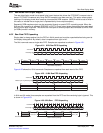
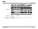
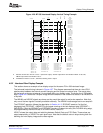
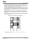
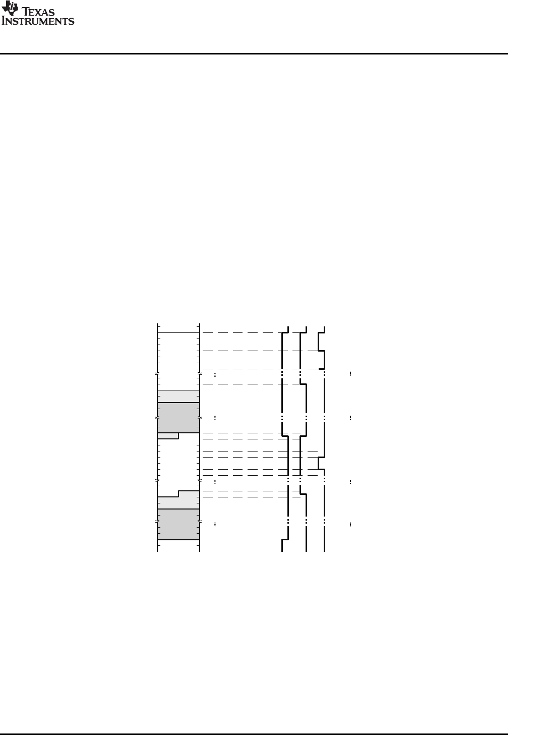
TheverticaloutputtimingforrawmodeisshowninFigure4-28.Thisexampleoutputsthesame480-line
window.Notethattherawdisplaymodeistypicallynoninterlacedforoutputtoamonitor.Thisexample
showsthemorecomplexinterlacedcase.Theactivefield1is242.5-lineshighandactivefield2is
242.5-lineshigh.Thisexampleshowsthe480-lineimagewindowcenteredinthescreen.Thisresultsin
anIMGVOFF1of2linesandanIMGVOFF2of3linesandalsoresultsinanon-datahalf-lineattheendof
field1andatthebeginningoffield2duetotheirnon-integerlinelengths.
TheVBLNKandVSYNCsignalsareshownastheywouldbeoutputforactive-lowoperation.Notethat
onlyoneofthetwosignalsisactuallyavailableexternally.TheVBLNKandVSYNCedgesforfield1occur
attheendofanactivelinesotheirXSTART/XSTOPvaluesaresetto720(startofblanking).Forfield2,
VBLNKandVSYNCedgesoccurduringthemiddleoftheactivehorizontallinesotheirXSTART/XSTOP
valuesaresetto360.
TheFLDoutputissetuptotransitionatthestartofeachanalogfield(startofverticalblanking).Thereis
noEAV[F]bitinrawmode,soFLD1YSTRTissetto1,FLD2YSTARTissetto263,FBITCLRand
FBITSETareignored.NotethatFLD2XSTRTis360sothatthefieldindicatoroutputchangeshalfway
throughtheline.
Theactivehorizontaloutputcolumnshowstheoutputdataduringtheactiveportionofthehorizontalline.
Notethatinrawmodethereisnoblankingdatavaluesothedefaultvalueisoutputfortheactiveportion
ofallnon-imagewindowlines.
Figure4-28.RawInterlacedDisplayVerticalTimingExample
AAssumesVCT1PbitinVPCTLissetto1(active-lowoutput).VSYNCoutputwhenVCTL2SbitinVDCTLissetto00,
VBLNKoutputwhenVCTL2Sbitisset01.
SPRUEM1–May2007VideoDisplayPort115
SubmitDocumentationFeedback


