


20 4200FA Installation and Operation Manual
CAUTION
Do not EPO (Emergency Power OFF) the UPS and then reset the
breaker until the UPS has been fully discharged. The UPS could be
damaged if the unit is not fully powered down before the breaker is
reset.
6 UPS Connections
Power Connections 6.1
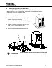
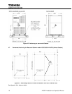
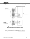
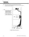
6.1.1 Power Connections 15/25/30 kVA with Internal Batteries
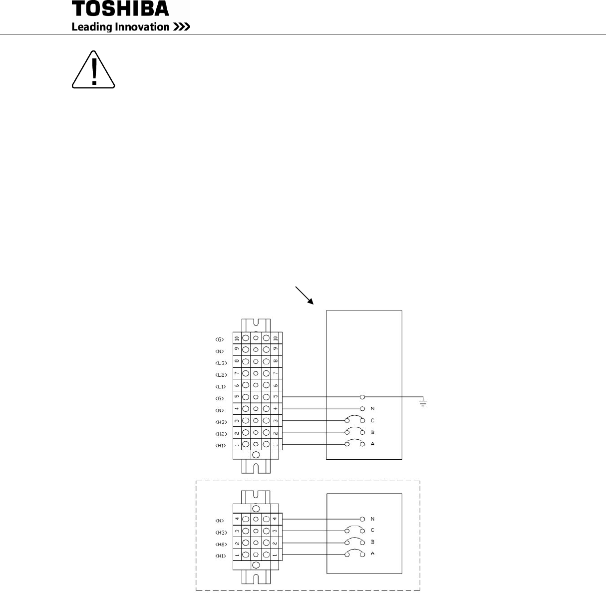
The following illustrates the wiring connections from the power distribution panel (not part of the
UPS) to the terminal block of the 15/25/30 kVA UPS Models. (Maximum wire capacity for TB1
and TB4 is 1 AWG.)
Ensure the three-phase commercial power input is connected for clockwise rotation. The UPS
output function is disabled if the input power is not phased for clockwise rotation.
* Customer-provided breaker for units with optional Bypass Input.
Figure 6-1 Power Cabling for 15-30kVA Units with Internal Batteries
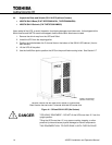
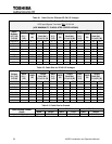
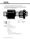
6.1.2 Power Connections 15/25/30 kVA with Internal Transformer
The following illustrates the wiring connections from the power distribution panel (not part f the
UPS) to the terminal block of the 15/25/30 kVA UPS Models. (Maximum wire capacity for TB1
and TB4 is 1 AWG.)
CUSTOMER-PROVIDED AC DISTRIBUTION PANEL
INPUT GROUND RESISTANCE
LESS THAN 10 OHMS
TB1
TB4
Optional Bypass Input:
3-phase, 3-Wire
*208 V requires 3-phase,
Input Terminals: 1 – 5
Output Terminals: 6 – 10