


4200FA Installation and Operation Manual 25
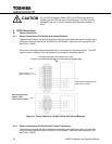
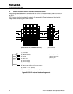
Control Circuit and External Battery Interface Connections 15/25/30 kVA 6.2
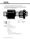
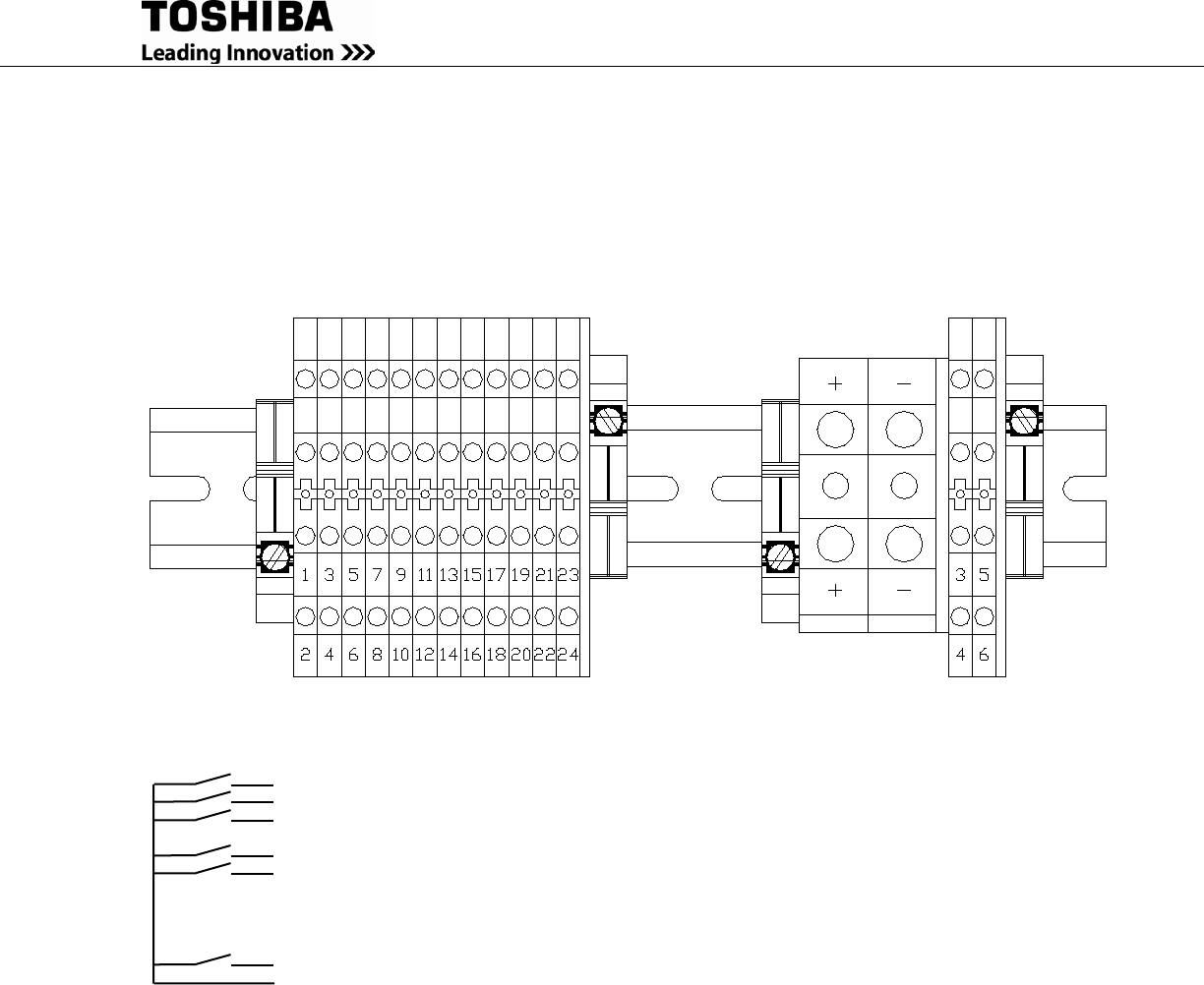
The following illustrates the wiring connections of the Control Circuits, and Battery Interface Circuits.
NOTE: Control circuit wiring should be routed in its own conduit. Do not route control circuit
wiring through conduit containing UPS power cables.
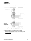
Figure 6-4 15-30kVA Control and Battery Terminals –TB-3
(1) Low Battery
(2) Battery Discharge
(3) Fault
(4) Not Used
(5) Inverter Supply
(6) Inverter Supply
(7) 24Vdc – 1A max. (P24A3)
(8) Remote Run (Switch UPS to Inverter Mode)*
(9) 24Vdc – 1 A max. (P24A3)
(10) Remote Stop (Switch UPS to Static Bypass)*
(11) Bypass
(12) COMMON
(13) EPO (24Vdc – 1A max.)
(14) EPO (24Vdc – 1A max.)
(15) – (24) Not Used
*Must be programmed in via the front panel
Battery Connection
(+) Positive
(-) Negative
(3) Battery Shunt Trip
(4) Battery Shunt Trip
(5) Battery Aux
(These terminals not available on Base units)
(These terminals on ALL units)