


32 4200FA Installation and Operation Manual
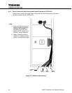
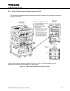
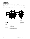
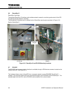
Control Circuit and External Interface Connections 50 kVA 6.4
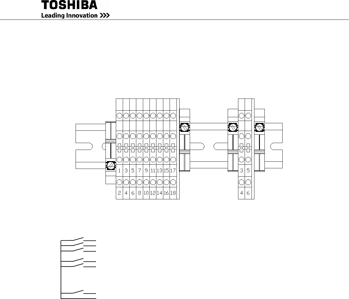
The following illustrates the wiring connections of the Control Circuits, and Battery Interface Circuits for
the 50kVA.
NOTE: Control circuit wiring should be routed in it’s own conduit. Do not route control circuit wiring
through conduit containing UPS power cables.
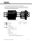
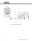
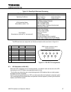
Figure 6-8 50kVA External Interface Assignments
(3) Battery Shunt Trip
(4) Battery Shunt Trip
(5) Battery Aux
(These terminals not available on Base units)
(These terminals
on ALL units)
(1) Low Battery
(2) Battery Discharge
(3) Fault
(4) Not Used
(5) Inverter Supply
(6) Inverter Supply
(7) 24Vdc – 1A max. (P24A3)
(8) Remote Run (Switch UPS to Inverter Mode)*
(9) 24Vdc – 1 A max. (P24A3)
(10) Remote Stop (Switch UPS to Static Bypass)*