


4200FA Installation and Operation Manual 27
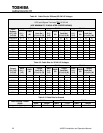
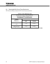
6.2.1 Recommended Wire Size and Torque Requirements
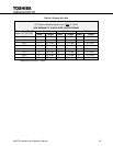
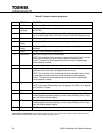
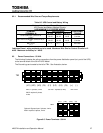
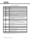
Table 6.6 UPS Control and Battery Wiring
*Indicates Class 1 wiring methods are to be used. Maximum Wire Size for Control Circuits is 12
AWG. Maximum for Battery is 1 AWG.
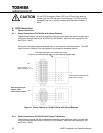
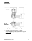
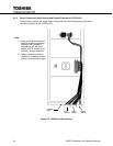
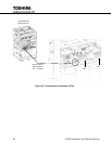
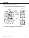
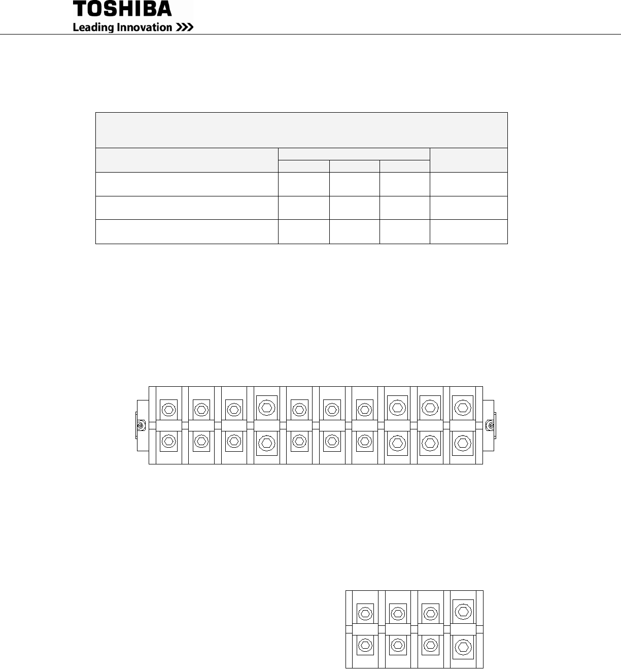
Power Connections – 50 kVA 6.3
The following illustrates the wiring connections from the power distribution panel (not part of the UPS)
to the terminal block of the 50 kVA UPS Model
The Ground lugs are located to the left of TB4. See illustration, below.
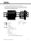
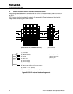
Optional: Bypass Input: 3-phase, 3-wire
Figure 6-5 Power Terminals - 50kVA
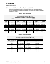
Minimum Wire Size and Torque Requirements
UPS Control and Battery Interface Circuits
USE MINIMUM 75 °C COPPER WIRING
TERMINAL
(TERMINAL #)
Wire Size AWG*
TIGHTENING
TORQUE
15 kVA
25 kVA
30 kVA
UPS CONTROL CIRCUITS
(1-24)*
14-16 14-16 14-16 8 in-lbs.
BATTERY CONTROL CIRCUITS (3-
6)*
14-16 14-16 14-16 8 in-lbs.
BATTERY
(+/-)
6 – 1 2 – 1 1 45 in-lbs.
Optional: Bypass Input: 3-phase, 4-wire
208 V requires 3-phase, 4-wire
(H1) (H2) (H3) (N)
(H1) (H2) (H3) (N) (L1) (L2) (L3) (N) (+) (-)
OUTPUT: 3-phase (4-wire)
INPUT: 3-phase, 3-wire
208 V requires 3-phase,
4-wire
TB1
TB4
BATTERY