


Vixel Model 335 Installation & Configuration Guide CHAPTER 3 Management
33
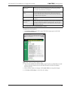
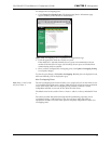
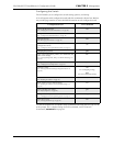
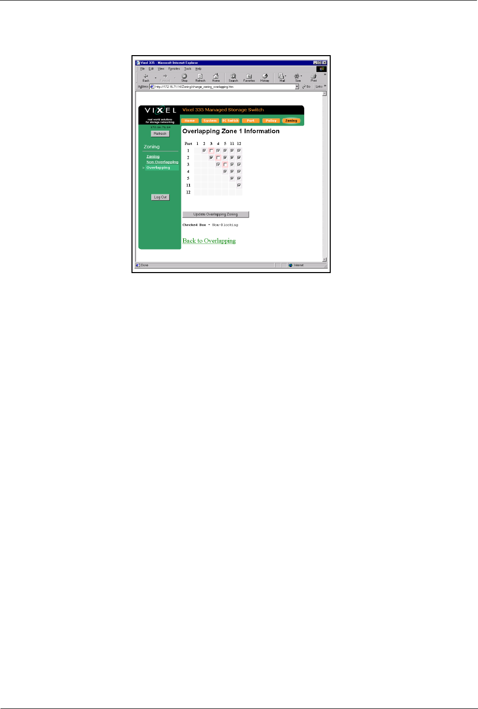
To configure the overlapping ports:
1. Click Change Overlapping Zones. The Overlapping Zone 1 Information page
appears with the ports available for modification.
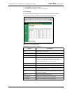
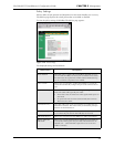
Figure 3-26. Overlapping Zone 1 Information (Configuration) Page
2. Click the appropriate check box for the two ports.
If the check box is selected (checked), the two ports can communicate with one
another. If the check box is empty (not checked), the two ports are blocked from
communicating with one another.
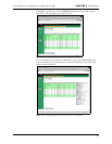
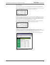
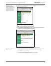
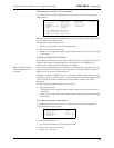
3. Once you have configured the overlapping ports, click Update Overlapping Zoning
to accept the changes.
To view the your changes, click Back to Overlapping. Blocked ports are displayed in red,
while non-blocked ports are displayed in gray.
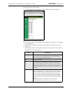
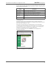
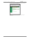
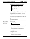
Non-Overlapping Zones
Note: Ports 11 and 12 can
only be in Zone 1.
The non-overlapping zones feature enables you to assign each port on the switch to one
of 12 available zones. Each zone is unique which allows for 6 separate zones to function
on the same switch. With non-overlapping zoning enabled, each zone is totally
independent and LIPs on one zone do not affect the other zones.
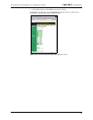
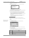
The default zone for the switch is Zone 1. Ports 11 and 12 are always included in Zone
1.
The switch provides LIP isolation through the LIP confinement properties of non-
overlapping zoning. A LIP occurring in one zone will never affect the traffic or
operations in another zone. Each zone operates completely independent of other non-
overlapping zones.