


Vixel Model 335 Installation & Configuration Guide CHAPTER 2 Installation
6
Note: FC-AL compatible
nodes must perform
initialization procedures
upon power-up in order to
function properly. It is the
responsibility of the Fibre
Channel driver software on
FC-AL nodes to perform
the initialization or re-
initialization (depending on
its prior state of operation).
4. Make sure the switch and any other connected switches or hubs are powered on.
5. Power on the storage devices (such as JBODs and RAIDs), then power on the hosts.
The network initializes.
6. Check all port LEDs. For more information on Port LED status, See “Port LEDs” on
page 7.
7. Check the green Switch Op (Switch Operational) LED. If the Switch Op LED is lit,
all zones with inserted devices are operational. If the Switch Op LED is blinking in a
multiple zone configuration, one or more zones are operational while others are not.
If the Switch Op LED is off, no operational zones exist or no devices are attached.
Note: Improper initialization could be the result of a defective or inoperative host
bus adapter card or device. Consult the vendor’s documentation for adapter diagnos-
tic procedures.
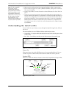
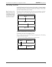
Understanding the Switch’s LEDs
You can check the system and port status through the Light-Emitting Diodes (LEDs) on
the switch.
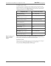
The switch utilizes two sets of LEDs to indicate switch and port status:
1. System LEDs – Six separate LEDs that indicate the status of the switch separate from
the Port LEDs.
2. Port LEDs – Two LEDs per switch port that indicate status of that specific port
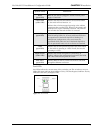
Figure 2-1. Switch features diagram
Power On
When powering on the switch, all LEDs turn on for two seconds and then off for two
seconds except for the Power LED, which remains lit while the switch is powered.
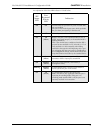
System LEDs
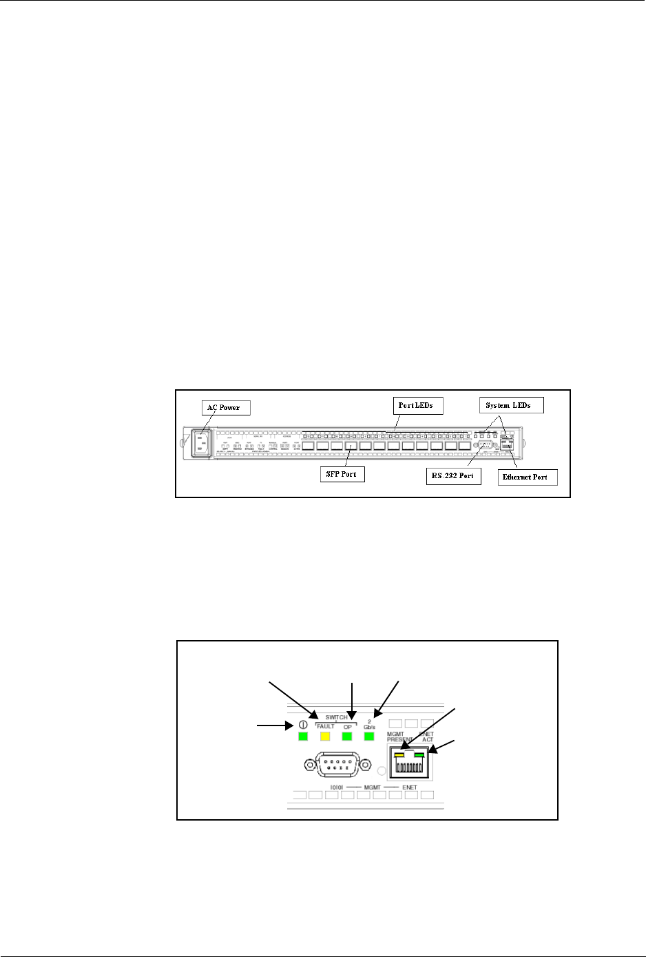
There are six LEDs that indicate the status of the switch, independent of the port LEDs:
Figure 2-2. System LEDs
Switch
Fault
Switch
Operational
Switch
Speed
Ethernet
Active
Management
Present
Power