


Data Connections
Serial Data Port
13163L Rev. 3 5/20/2004 Z4Mplus/Z6Mplus User Guide 103
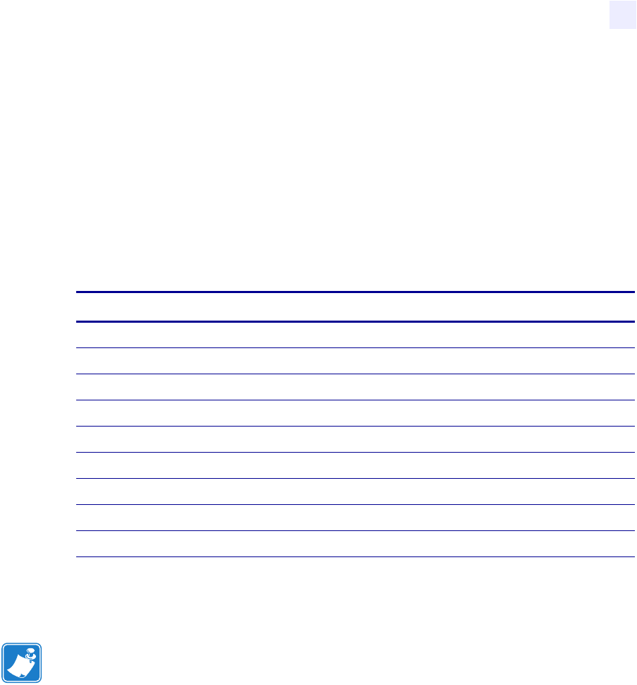
RS-232 Serial Data Port
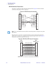
The connection for this standard interface is made through the female DB-9 connector on the
rear panel. A DB-9 to DB-25 interface module is required for all RS-232 connections through
a DB-25 cable (see RS-232 Interconnections Using a DB-25 Cable on page 105 for details).
For all RS-232 input and output signals, the printer follows both the Electronics Industries
Association’s (EIA) RS-232 specifications and the Consultative Committee for International
Telegraph and Telephone (CCITT) V.24 standard signal level specifications.
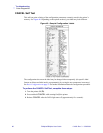
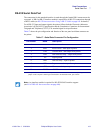
Table 17 shows the pin configuration and function of the rear panel serial data connector on
the printer.
Table 17 • Serial Data Connector Pin Configuration
Pin Number Name Description
1 — Not connected
2 RXD Receive data—data input to printer
3 TXD Transmit data—data output from printer
4 DTR Data terminal ready—output from printer
5 SG Signal ground
6 DSR Data set ready—input to printer
7 RTS Request to send—output from printer
8 CTS Clear to send—input to printer
*9 +5 V DC +5 VDC
* This pin is also available as a +5 VDC power source at 750 mA. To enable this capability, a
jumper on the computer’s main logic board needs to be installed on JP1, pins 2 and 3.
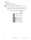
Note • An interface module is required for RS-422/RS-485 interface support
(see RS-422/RS-485 Interconnections on page 106).