


IES-1000 User’s Guide
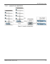
2-2 Hardware Overview
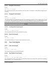
Table 2-1 Network Module LED Descriptions
LED COLOR STATUS DESCRIPTION
SHDSL (1-8) Green Blinking The DSL ports are being tested or have failed.
or On The DSL link is up.
ADSL (1-8) Off The DSL link is down.
LAN Green Blinking The system is transmitting/receiving to/from a 10 Mbps Ethernet
network.
On The link to a 10 Mbps Ethernet network is up.
Off The link to a 10 Mbps Ethernet network is down.
Yellow Blinking The system is transmitting/receiving to/from a 100 Mbps Ethernet
network.
On The link to a 100 Mbps Ethernet network is up.
Off The link to a 100 Mbps Ethernet network is down.
2.2.2 Front Panel Ports
The following tables describe front panel ports.
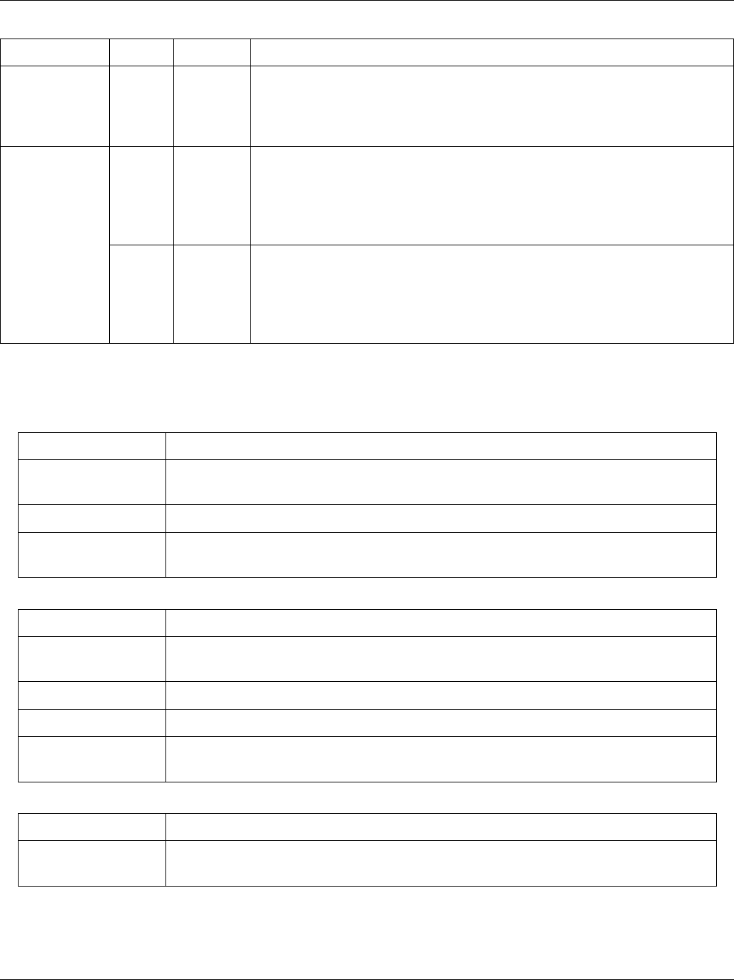
Table 2-2 Front Panel Ports of the SAM1008 Network Module
PORT DESCRIPTION
LAN The LAN port is a 10/100 Mbps auto-sensing Ethernet port that connects to a
router.
SHDSL 1-8 These RJ-11 ports (labeled 1-8) connect to subscriber G.SHDSL equipment.
CONSOLE The CONSOLE port is an RJ-11 port used for configuring the IES-1000. This
port connects to a local computer.
Table 2-3 Front Panel Ports of the AAM1008 Network Module
PORT DESCRIPTION
LAN The LAN port is a 10/100 Mbps auto-sensing Ethernet port that connects to a
router.
ADSL 1-8 (upper) These RJ-11 ports (labeled 1-8) connect to subscriber ADSL equipment.
ADSL 1-8 (lower) These RJ-11 ports (labeled 1-8) connect to CO (central office) equipment.
CONSOLE The CONSOLE port is an RJ-11 port used for configuring the IES-1000. This
port connects to a local computer.
Table 2-4 Front Panel Ports of the IES-1000
PORT DESCRIPTION
POWER The POWER port accepts power from the included power cord. Refer to
section 1.2.4 for specifications.