INSTALLATION
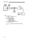
Make Emergency Transfer Connections
Note:
The following procedure assumes that the network interfaces
1.
2.
3.
4.
5.
6.
7.
are connected to the 700A jacks and connector 0 of the 3:1
splitter cables has been connected to the jack. See Install
Equipment Room Trunk Cabling in this part.
Connect Trunk Lines From Cabinet to ETU
Using the cable label sheets provided (Figure 2-7), label both ends of
a B25A cable. Use a cabinet number and slot number (CAB1
SLOT8, for example) and the label SWITCH (TRUNK) on each end.
Position the labels on the rear hood of the connectors.
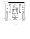
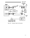
Connect the female end of the B25A cable to the connector marked
SWITCH (TRUNK) and the male end to the appropriate CO trunk CP
(ZTN76 or ZTN77) on the rear of the system cabinet.
Connect Port Lines From Cabinet to ETU
Label both ends of a B25A cable. Use a cabinet number and slot
number (CAB1 SLOT8, for example) and the label SWITCH (LINE) on
each end. Position the labels on the rear hood of the connectors.
Connect the female end of the B25A cable to the connector marked
SWITCH (LINE) and the male end to the appropriate station CP
(TN742 or ZTN78) on the rear of the system cabinet.
Connect 3:1 Splitter Cable to ETU
Label both ends of a 3:1 splitter cable. Use the label that identifies
the ETU number (ETU1 CO, for example) on connector O end and on
one leg of the cable (leg 3 contains the DID make-busy pair, if
provided). Position the Iabels on the rear hood of the connectors.
Connect the appropriate leg (1, 2, or 3) of the splitter cable to the CO
receptacle on the ETU.
Connect ETU to SIP
Label the flag tie-wrap and 25-pair connector of an octopus cable.
Use Iabel that identifies ETU number (ETU1 SIP, for example) on the
connector. Position the label on the rear hood of the connector.
2-80


