


INSTALLATION
Initialize System
Instructions
for initializing the system
(based on the completed
implementation
forms) are provided in the Administration Manual
(555-540-500).
Note:
Before trunks using DS1 Signaling are administered, all link
level parameters such as signaling and framing and all link
level alarms must be cleared. If this is not possible, PBXs at
each end will not work.
If this condition exists, clear a
maintenance busy condition that exists at each end.
INSTALL CROSS-CONNECT EQUIPMENT
Before starting, familiarize yourself with the following equipment described in
CROSS-CONNECT EQUIPMENT DESCRIPTION:
● Trunk Access Equipment (TAE)
● Station
700 A-110-B1 -25 or 700A-66-B1-25 Wiring Jacks
10B Emergency Transfer Units
Interconnect Panel (SIP)
617A Panels
858A or Z210A2 Adapters
50A Fanning Strips.
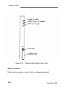
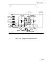
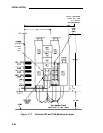
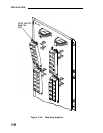
Figure 2-16 shows a typical SIP and TAE backboard layout. Figure 2-17
shows an alternate layout that can be used when horizontal wall space is
limited. These layouts can be reversed when the switch cabinet(s) must be
installed to the right of the backboard.
2-43