


INSTALLATION
connector and a KS23146,L3 50-pin male connector.
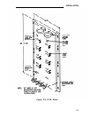
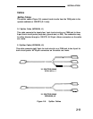
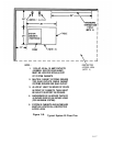
To connect a DS1 interface circuit pack to a 551-type
Unit (CSU), field terminate the 15-pin plug.
To connect DS1 tie trunks on co-located System 25s,
50-pin male connector (see Figure 2-1 9).
Customer Service
field terminate the
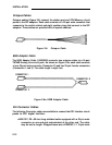
● C6E connector cable (comcode 104307 434)—1 00-foot long shielded
cable equipped with a 50-pin male connector on one end and a 50-pin
female connector on the other end. This cable is used as an
“extension” cable between the DS1 Interface circuit pack and the other
connector cables.
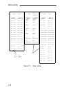
Cable Labels
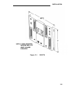
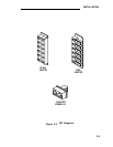
A set of preprinted labels for identifying the system cabinet cables and ETU
cables are provided (Figure 2-7). The system cable labels are prenumbered to
identify the cabinet (1, 2, 3) and circuit pack slot (1-12, - see NOTE) and are also
color-coded as follows:
Note: Because of the combined CP/Memory board in R2V1 and R3,
ten slots are available in Cabinet 1.
I
Cabinet No.
Color
I
1
Blue
2
Orange
3
Green
The call processor octopus cable labels and ETU cable labels are white. The
use of these labels is discussed in this manual.
2-13