


INSTALLATION
PREINSTALLATION REQUIREMENTS
The AT&T System 25 Reference Manual (555-540-200) provides a complete
listing of System 25 equipment location requirements. Before installation
begins, check the items described in this section.
Caution: System 25 cross connect hardware must be located in a
restricted access area only.
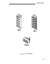
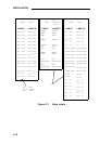
Table and Backboard
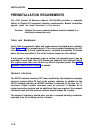
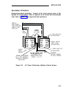
Verify that an equipment table and cross-connect backboard are installed.
(See Figure 2-8 for a sample layout.) The cross-connect backboard is a 48-
inch by 96-inch by 3/4-inch plywood panel, mounted horizontally 30-inches
above the floor and within 5 feet of the location chosen for the cabinets.
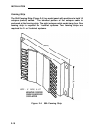
If wall space in the equipment room is limited, an alternate layout may be
provided. If more than four 617A Panels are required, this alternate layout
will require more than one 48-inch by 96-inch plywood panel. See Install
Equipment Room Station Cabling for details.
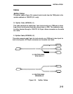
Network Interface
The RJ21X network interface (CO lines) installed by the telephone company
must be located within 25 feet of the system cabinets. In addition to the
RJ21X network interface, an RJ2GX interface is required for tie
lines. For T1
interfaces, RJ48X network interfaces must be provided.
If System 25 is
replacing another system and no additional lines are required, the network
interfaces used with the previous system should already be in place.
The network interfaces should also include a coupled bonding conductor
extended from the building service entrance.
2-16