


INSTALLATION
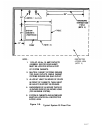
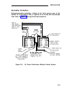
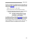
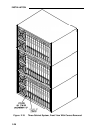
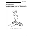
Two fans are located on the left-hand front side of each cabinet. The
cabinet’s power supply is located behind the fans; to the right of the power
supply are up to 12 CPs in individual slots.
Each CP is identified by a label
on the front. See Figure 2-10.
1.
Remove the front cover of each cabinet.
2. Note any obviously bent or otherwise damaged circuit packs.
3. Check the CPs against the customer order. In case of irregularities
or damage, follow established notification procedures.
Danger: The System 25 cabinet contents are not user
serviceable. Some voltages inside the cabinets
are hazardous.
This equipment is to be
serviced only by qualified technicians.
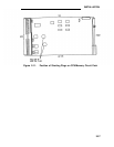
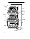
The CPU/Memory (ZTN129 or ZTN130 [R3]) circuit pack has two shorting
plugs that are used for factory tests (see Figure 2-1 1). They should have
been removed at the factory.
If these shorting plugs have been accidentally
left in by the factory, the system may cold start when it should warm start.
Check the CPU/Memory CP; if the plugs are present, remove them. The
shorting plugs are located on the component side of the circuit pack.
2-25