


INSTALLATION
Connect Cabinets
The Time Division Multiplex (TDM) bus extender cable and the intercabinet
#6 AWG ground wire must be connected between cabinets. The TDM bus
terminates on each side of the cabinet, and the intercabinet #6 AWG ground
wire connects to the ground block at the rear of each cabinet.
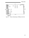
Note:
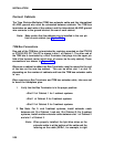
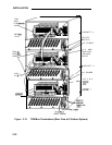
Make certain that the address plug is installed in the rear pin
field of each cabinet (see Figure 2-13).
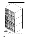
TDM Bus Connections
One end of the TDM bus is terminated by resistors mounted on the ZTN129
or ZTN130 (R3) CP. This CP is always in slot 1 of Cabinet 1. The other end of
the TDM bus is terminated by a Bus Terminator that plugs into the upper pin
field of the topmost carrier (which may, of course, be the only cabinet). These
connections are shown in Figure 2-13.
Whenever a cabinet is added, the Bus Terminator must be moved to the end
of the bus on the new top cabinet.
This can be either slot 1 or slot 12,
depending on the number of cabinets and how the TDM bus extender cable
is run.
When removing a Bus Terminator and TDM bus extender cable,
to bend the backplane pins.
1.
Verify that the Bus Terminator is in the proper position:
● Slot 12 of Cabinet 1 for 1-cabinet systems
● Slot 1 of Cabinet 2 for 2-cabinet systems
● Slot 12 of Cabinet 3 for 3-cabinet systems.
take care not
2. See Note. For 2- and 3-cabinet systems, install extender cable
between slot 12 of Cabinet 1 and slot 12 of Cabinet 2. For 3-cabinet
systems, install another extender cable between slot 1 of Cabinet 2
and slot 1 of Cabinet 3.
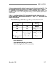
Note:
When properly installed, the light blue stripe on the
extender cable is at the bottom of the cable and the
lettering on the cable (SER=1, for example, is right
2-30