


APPENDIX C: System Additions or Changes
Add Trunk
1.
2.
3.
4.
5.
6.
If you are adding a DID or tie trunk, evaluate the cabinet unit power
load using the procedures under Evaluate Cabinet Unit Power Load
in this appendix.
Check to see that the trunk has been connected to an RJ21X (for a
DID trunk) or RJ2GX (for a tie trunk) network interface by the
telephone company.
If the trunk is connected to an existing network interface, determine
the correct wires on the connecting cable. Cut them down to the
correct position on the TAE connecting block, following the
procedures under “Install Cross-Connect Equipment” in Section 2.
If the trunk is connected to a new network interface, connect it to the
TAE following the procedures under “Install Cross-Connect
Equipment” in Section 2.
Install the correct CP as described under
“Add Circuit Pack” in this appendix. Connect a plug from the
splitter cable to the connector of the above CP at the back side of
the cabinet.
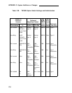
Install secondary wiring protectors. (See Table 2-B.)
Follow standard procedures for translating the trunk port using the
SAT.
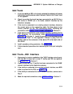
Add Trunk—DS1 Interface
1.
2.
3.
4.
5.
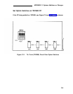
Determine if a trunk is available at
with the SAT. If there isn’t, a new
Use “Install DS1” in Section 2.
the TN767 Interface circuit pack,
T1 facility and CSU are required.
Check to see that the T1 facility has been connected to the RJ48X
network interface by the telephone company.
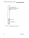
If the facility is connected to an existing network interface, use MOD
cable to connect to the CSU, see Figure C-3.
If the facility is connected to a new network interface, connect as in
Step 3.
Make the required connections using “INSTALL DS1” in Section 2.
C-11