


INSTALLATION
Install
DS1
DS1 signaling allows a digital connection between the System 25 and other
PBXs, Central Offices, Toll Offices, off premise stations, and data end points
such as host computers. The TN767 emulates ground start, Ioopstart, tie and
DID Trunks in addition to off premises stations. The ZTN131 circuit pack
provides the required digital synchronization.
The TN748 circuit pack will provide
the Touch Tone registers.
The term synchronization refers to an arrangement where by digital facilities
operate from a common clock.
This allows the receiving facilities to keep the
digital signals in step or synchronized.
Synchronization can be provided by the
system 25 any other PBX it is connected to, or by the CO being used by the
network, Synchronization must be properly engineered before installation is
begun. Each node must be aware of the synchronization plan so that it may be
properly administered.
The TN767 circuit pack generates a signal that is shaped in a manner that when
it reaches the cable it conforms to power specifications. The level of the signal
must be adjusted according to the cable distance. If the DS1 Interface
terminates at the cross connect field or at a CSU, the total cabling distance must
be used. If the DS1 Interface terminates on another PBX (direct connection), a
phantom point midway between the two PBXs should be used as the reference
point. The line equalization/compensation for S25 is set via administration
procedures from the SAT.
Connect S25 to Another On Premises PBX
When the S25 and the other PBX are in the same building, the cabling is broken
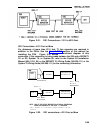
down into three different distance ranges. The first connection is for distances of
1310 feet or less. The second distance range is 1311 to 4310 feet which
requires the use of a Customer Service Unit (CSU) equipped with an Office
Repeater. The third distance range is greater than 4311 feet. It uses a CSU and
T1 line repeaters as required.
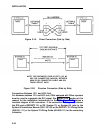
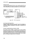
Direct Connection—Less Than 1310 Feet
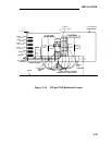
Figures 2-19 and 2-20 show two different direct connections. Figure 2-19 is
normally used for connecting a S25 to another PBX that is virtually side by side.
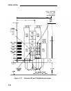
Figure 2-20 is used for direct connections that involve more distance. Figure
2-20 shows two S25s but a DEFINITY G1 or G2, System 75, or System 85 can
be connected directly to the S25. Consult the System 85 installation manual
(555-103-104) or the DEFINITY G1 Wiring Guide (555-204-111) or the System
75 Wiring Guide (555-200-111) for the connection information for those PBXs.
2-53