


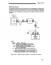

Nonswitched
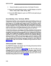
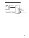
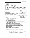
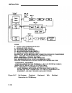
See Figure 2-46.
Connection of Equipment
Note:
Figure 2-46 shows an Z210A1 SIP Adapter to provide the
building wiring termination.
An 858A Adapter can also be
1.
2.
3.
4.
5.
6.
7.
8.
9.
10.
used.
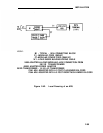
Connect the RS-232C plug on the peripheral
232C port on a Z3A1 or Z3A4 ADU.
Always
other fasteners on this connection.
equipment to the RS-
tighten the screws or
Connect the ADU to the building wiring with a D8W-87 modular
telephone cord.
At the SIP, connect the building wiring termination to an Z210A1
Adapter.
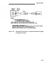
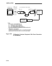
Locate the Z210A1 Adapter connected to the desired call processor
port. Connect a D8W-87 modular telephone cord to a Z210A1
Adapter jack.
Connect the other end of the modular cord to a 355AF Adapter.
Connect an M7U-87 Cord to the 355AF Adapter.
Connect the other end of the M7U cord to the RS-232C jack on a
Z3A4 ADU. Always tighten the screws or other fasteners on this
connection.
Connect the ADU to a 400B2 Adapter with two series connected
modular cords, D8W-87 and D8AM-87, as shown in Figure 2-46.
Connect the 400B2 Adapter to a 2012D supplementary power unit
with a D6AP Cord, as shown.
Plug the 400B2 Adapter into the SIP appearance (858A Adapter jack)
of the peripheral equipment.
2-104