INSTALLATION
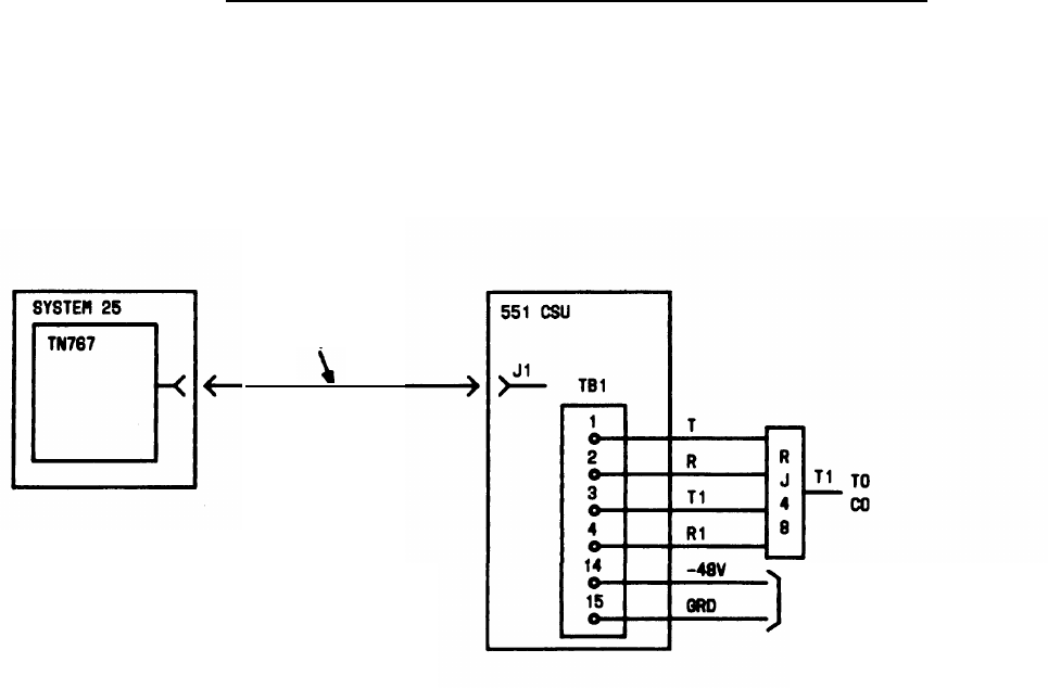
Connect the CSU
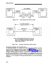
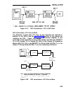
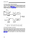
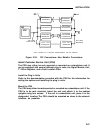
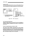
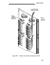
The CSU can be powered by the line or from a locally provided -48 V dc
power supply. Figure 2-25 shows the connections for connecting the CSU.
The 48 V and GRD leads are optional according to how the CSU is powered.
H600 307 ,02
CONNECTOR
CABLE (NOTE)
NOTE : FOR DISTANCES OVER 50 FEET ( 15.2 M)
USE C6E CONNECTOR CABLE(S) BETWEEN
H600 307,02 CONNECTOR CABLE AND DS1
TRUNK CIRCUIT PACK .
TO LOCALLY
PROVIDED -48V
POWER SUPPLY
Figure 2-25. CSU Connections
Line Compensation/Equalization
Determine the cable distance of the line, either to the line termination or
“phantom” midpoint of a direct connection.
Refer to the System 25
Administration Manual (555-540-650) for instructions on setting the line
equalization.
Connect Coupled Bonding Conductor (CBC)
Each network interface (RJ48X) is associated with a service entrance
(protector block) ground. A CBC should be connected to this ground. If the
local telephone company has not run a CBC up to the network interface, you
should run it yourself. Use #12, #14, or #16 AWG wire. Start the CBC at
the protector block ground, and run it as close as possible to the facilities
cable. If possible, tie wrap the CBC to the facilities cable. Do not use spare
pairs in the telephone company cable for this purpose.
2-58


