


Getting Started 13Chapter 1
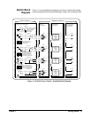
Switch Block
Diagram
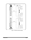
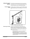
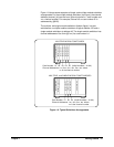
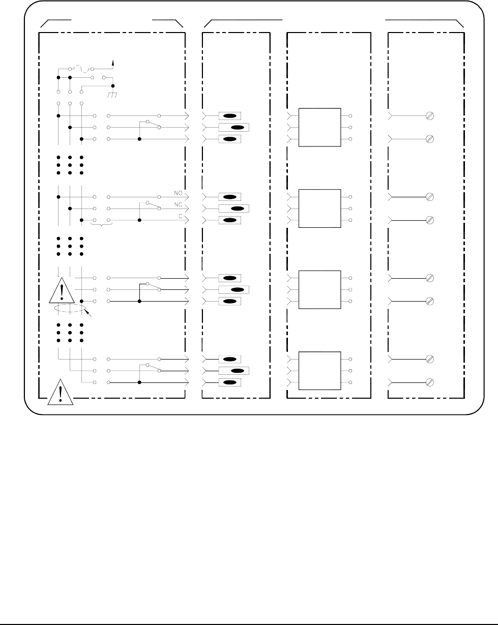
Figure 1-2 is a simplified block diagram of the Form C switch with internal
bus and available terminal modules (Standard, Option 010, and Option 020).
Figure 1-2. E1442A Form C Switch - Simplified Block Diagram
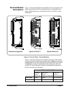
Terminal Module
terminals to the internal bus
to 42 VDC or 60V Peak AC
(NO, NC or C) restricts the
Use of any internal bus
maximum switched voltage
NC
NO
NC
NO
Channel 63
Channel 32
C
C
CH 63
CH 32
connect the NO, NC or C
components or jumpers to
to install user supplied
All channels have locations
SWITCH MODULE
at power down
latching relays that open
All channels use non-
64-Channel Form C Switch Module
+5V Pullup
E1442A
1A Max
See "Using the Internal
jumper information
NC
NO
Channel 31
internal buses
when using the
Buses" for component/
Channel 00
CH 31
C
CH 00
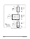
Solder-Lug
Standard
Conditioning
Signal
And
Jumpers
Circuitry
Conditioning
Signal
And
Jumpers
Circuitry
C
NO
NC
NC
C
NO
NO
C
NC
CH 63
NO
CH 32
C
NC
C
NO
CH 63
CH 32
C
NO
(Screw Terminals)
Option 020
Form A Configuration
Terminal Module
Conditioning
Signal
And
Jumpers
Circuitry
Jumpers
And
Circuitry
Conditioning
Signal
NC
C
NO
NO
C
NC
NO
CH 31
C
NC
CH 00
C
NC
NO
Terminal Module
Signal Conditioning
Option 010
TERMINAL MODULES
CH 31
C
NO
CH 00
NO
C