


94 Register-Based Programming Appendix B
Register Definitions
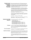
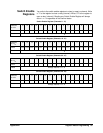
Manufacturer ID Register (read-only register)
Address
b+00
16
15 14 13 12 11 10 9 8 7 6 5 4 3 2 1 0
Read
Manufacturer ID; Returns
FFFFh = Hewlett-Packard A16 only register-based device.
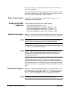
Device Type Register (read-only register)
Address
b+02
16
15 14 13 12 11 10 9 8 7 6 5 4 3 2 1 0
Read
Returns
0228
16
for the E1442A module.
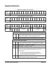
Status/Control Register
Address
b+04
16
15 14 13 12 11 10 9 8 7 6 5 4 3 2 1 0
Write* Undefined D Undefined R
Read** Un-
def
MUn-
def
S1 Undefined B D Undefined R
*Write Bits (Status/Control Register)
bit 0 R
Writing a 1 to this bit resets the switch to the power-on state (all channels
open). To reset, keep this bit set to 1 for a minimum of 100 ms and then
set bit 0 back to a logical 0 to allow switches to be closed.
bit 6 D
Disable interrupt by writing a 1 to this bit (set back to 0 with a reset).
**READ BITS (Status/Control Register)
bit 0 R
A 1 at this bit resets the switch to the power-on state (all channels open).
To reset, set bit 0 back to a logical 0 to allow switches to be closed.
bit 6 D
Interrupt Status: 1 = disabled, 0 = enabled.
bit 7 B
Busy Status: 1 = not busy, 0 = busy.
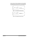
bit 12 S1
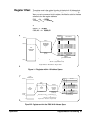
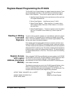
Fuse F4 provides +5V pull-up voltage for the NC and NO switch contacts
by use of the module’s internal bus (see Figures 1-8 and 1-9.)
Fuse F4 status;
0 = fuse F4 not installed (factory shipped without the fuse).
(A 0 also can indicate a blown fuse after installing fuse F4.)
1 = fuse F4 is installed (user must install fuse).
bit 14 M
MODID bit; if the bit is 0, the module has been selected during turn-on.
Normally this bit is 1 when not in the turn-on cycle.