


88 Register-Based Programming Appendix B
The Base Address When reading or writing to a switch register, a hexadecimal or decimal
register address is specified. This address consists of a base address plus
a register offset. The base address used in register-based programming
depends on whether the A16 address space is outside or inside the E1406
Command Module.
A16 Address Space
Outside the Command
Module
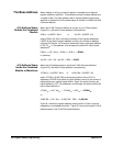
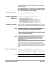
When the E1406 Command Module is not part of your VXIbus system
(Figure B-1), the switch’s base address is computed as:
C000
16
+ (LADDR * 64)
16
or 49,152 + (LADDR * 64)
where C000
16
(49,152) is the starting location of the register addresses,
LADDR is the switch’s logical address, and 64 is the number of address
bytes per VXI device. For example, the switch’s factory-set logical address
is 120 (78
16
). If this address is not changed, the switch will have a base
address of:
C000
16
+ (120 * 64)
16
= C000
16
+ 1E00
16
= DE00
16
or (decimal)
49,152 + (120 * 64) = 49,152 + 7680 = 56,832
A16 Address Space
Inside the Command
Module or Mainframe
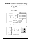
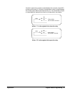
When the A16 address space is inside the E1406 Command Module
(Figure B-2), the switch’s base address is computed as:
1FC000
16
+ (LADDR * 64)
16
or 2,080,768 + (LADDR * 64)
where 1FC000
16
(2,080,768) is the starting location of the VXI A16
addresses, LADDR is the switch’s logical address, and 64 is the number of
address bytes per register-based device. Again, the switch’s factory-set
logical address is 120. If this address is not changed, the switch module will
have a base address of:
1FC000
16
+ (120 * 64)
16
= 1FC000
16
+ 1E00
16
= 1FDE00
16
or
2,080,768 + (120 * 64) = 2,080,768 + 7680 = 2,088,448
Figure B-1 shows the register address location within A16 as it might be
mapped by an embedded controller. Figure B-2 shows the location of A16
address space in the E1406 Command Modules.