


50 E1442A Application Examples Chapter 2
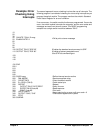
1. ,1,7 (line 50) closes channel 100.
2. Closure causes trigger to be output from Trig Out port.
3. Trigger to Ext Trig In initiates channel 100 measurement.
4. Channel 100 measurement result stored in instrument.
5. Trigger is then output from Measurement Complete port.
6. Trigger to Event In port advances scan to channel 101.
7. Steps 2-6 are automatically repeated for channels 101-102.
10 OUTPUT 722;"TRIG EXT; .... "
! Configure voltmeter
20 OUTPUT 70915;"OUTP ON"
! Enable Trig Out port
30 OUTPUT 70915;"TRIG:SOUR EXT"
! Event In triggering
40 OUTPUT 70915;"SCAN (@l00:102)"
! Scan channels 00-02
50 OUTPUT 70915;"INIT"
! Enable scan.
60 FOR Chan = 1 to 3
70 PRINT "Channel", Chan, Result
80 NEXT Chan
90 OUTPUT 70915;"*RST"
! Reset module and open last
! switch closed
100 END
Example:
Synchronizing the
Form C Switch
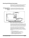
This example discusses synchronizing the switch to other instruments when
making measurements. The following example uses the switch module to
switch a signal to be measured by a multimeter. The program verifies that
the switching is complete before the multimeter begins a measurement.
The measurement setup consists of a Digital Multimeter with a GPIB select
code = 7, primary address = 09 and secondary address = 03 (addressed as
70903) and an E1442A with a GPIB select code = 7, primary address = 09
and secondary address = 15 (addressed as 70915).
10 OUTPUT 70915;"CLOS (@100)"
! Close channel 100
20 OUTPUT 70915;"*OPC?"
! Wait for completion of close ! command
30 ENTER 70915;Opc_value
! Read response to *OPC? command.
31 !
32 ! Channel is closed and the measurement can be made.
33 !
40 OUTPUT 70903;"MEAS:VOLT:DC?"
! Make VM measurement
50 ENTER 70903;Meas_value
! Read the measurement
60 PRINT Meas_value
! Print the measurement
70 END