


32 Getting Started Chapter 1
Example: Common
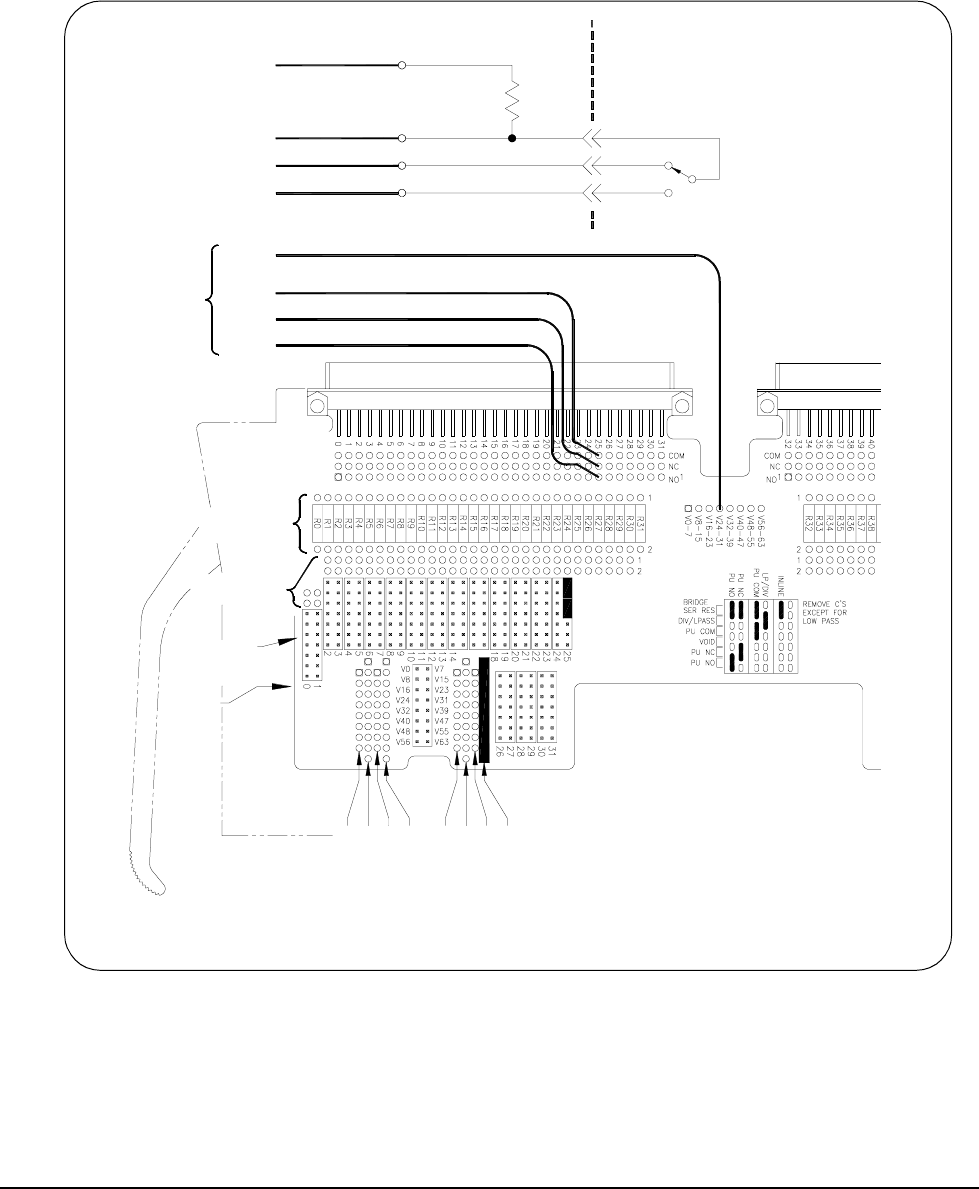
Terminal Pullup
Configuration
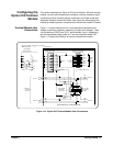
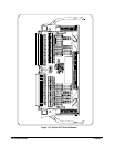
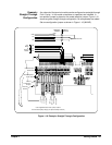
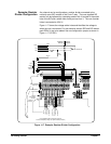
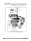
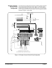
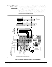
Any channel can be configured as a pullup (or pulldown) resistor connected
to any of the contacts of the Form C relay. Figure 1-19 shows a typical
channel 25 with the pullup attached to the COM contact. For this example,
the SIP resistor pack RP24-31 is to be added. Set two configuration jumpers
as shown in Figure 1-19 (PU COM).
Figure 1-19. Example: Common Terminal Pullup Configuration
TERMINAL
MODULE
SWITCH
MODULE
Channel 25
RP
24-31
R
P
0
-
7
V
8
-
1
5
V
0
-
7
R
P
8
-
1
5
V
1
6
-
2
3
R
P
1
6
-
2
3
V
2
4
-
3
1
R
P
2
4
-
3
1
COM
NO
NC
NO
NC
Vpullup
V24-31
COM
Voltage
Module
Terminal
To
Wiring
User
NO
NC
Pullup
COM
User Supplied Resistor Packs (SIP) Locations
and associated pullup voltage (for optional standup resistors)
Channel Capacitor
Solder Holes
Jumpers
Configuration
Channel
Channel
Number
Solder Holes
Channel Resistor