


Getting Started 27Chapter 1
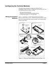
Configuring the
Option 010 Terminal
Module
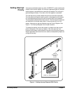
This section describes the Option 010 Terminal Module. With this terminal
module, you can add components to configure a variety of passive signal
conditioning circuits including pullups, pulldowns, and single-ended and
differential resistive dividers and filters. User inputs are connected to the
module by soldering wires or components to the terminal module PC board.
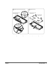
Terminal Module User
Connections
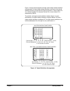
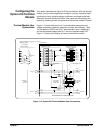
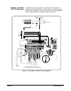
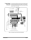
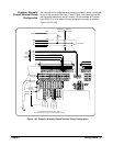
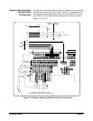
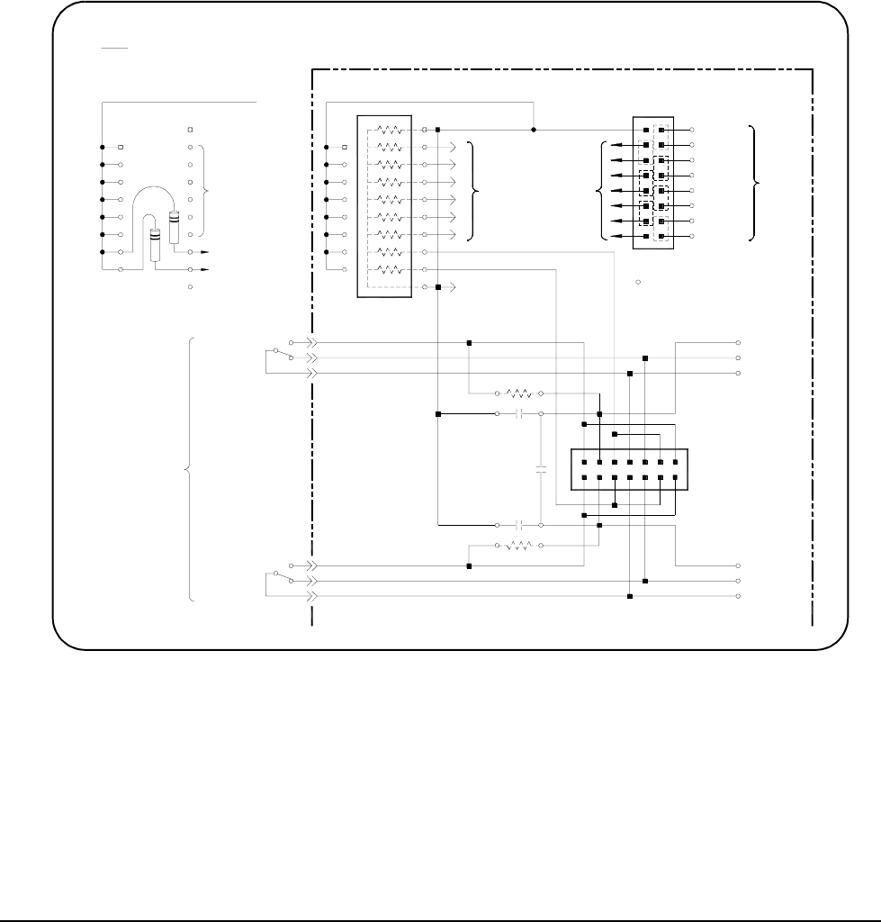
Figure 1-14 shows channels 0 and 1 and associated component and
voltage connections (resistors, capacitors, jumpers and voltages). Note
the correlation of R0/C0 and R1/C1 with channels 0 and 1 respectively
and the associated voltage node V0-7 and user-supplied resistor SIP.
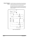
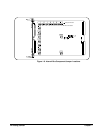
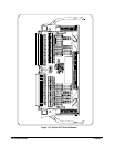
Figure 1-15 shows the locations of items on the terminal module.
Figure 1-14. Option 010 Terminal Module User Connections
Connections for 2 of 64 Channels
Channel 0
Channels
Module
Component
Com
NC
NO
Channel 1
a) Discrete Standup
Note: User Supplied Pullup resistors can be either
Standup Resistors
User Supplied
Resistor Pack (SIP)
CH0
CH1
Channels
2-7
To
Com
NC
NO
User Supplied
b) Resistor Pack or
R1
R0
Components
Divider/Filter
User Supplied
C0
C1
Channel 0
NO’
NC
Com
Configuration
Channel Pair
Jumpers
= PC Board Solder Hole
Common To All Banks
Making A Pullup Voltage
Jumper Locations For
8-63
Channels
To Channels
2-7
Channels
2-7
To
To
Channel 1
Com
NC
NO’
V56-63
V8-15
V48-55
V40-47
V32-39
V24-31
V16-23
V0-7
Inputs
Voltage
Pullup
Module