


48 E1442A Application Examples Chapter 2
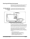
Scanning with External Instruments
Scanning Form C switch channels has the same effect as executing multiple
CLOSe commands. Thus, scanning is useful when the outputs from a
number of devices under test (DUTs) are to be measured with an
instrument. Three examples using BASIC programming language follow.
Example: Scanning
with External
Device
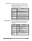
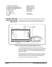
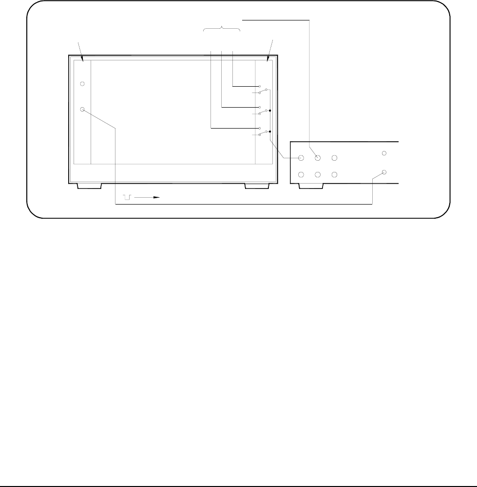
This example uses the E1406 Command Module Trig Out port to
synchronize the Form C switch channel closures to an external
measurement device. See Figure 2-2 for typical user connections.
For measurement synchronization, the E1406A Trig Out port is connected
to the external instrument (3458 Voltmeter) External Trigger In port. For this
example, the mainframe and instrument are connected via GPIB with the
mainframe at address 709 and the measurement instrument at address 722.
The Form C switch is at logical address 120 (secondary address 15 and
therefore address through the mainframe at address 70915). The
measurements are transferred directly to the computer. Appropriate
instrument commands must be added to line 10. Also, you may need to
add a WAIT statement as line 65 for long measurements. The sequence of
operations is:
1. ,1,7 (line 50) closes channel 100.
2. Closure causes trigger output from the Trig Out port.
3. Trigger to Ext Trig In initiates channel 100 measurement.
4. Result is sent to the computer (lines 60-80).
5. 75,**(5 (line 90) advances the scan to channel 101.
6. Steps 2-5 are repeated for channels 101-102.
Figure 2-2. Example: Scanning with an External Device
E1401 Mainframe
E1406A
Trig
Out
Trig
In
To DUTs
C
H
0
C
H
2
C
H
1
Ext Out
HI
HI
LO
LO
G
I
Ext Trig
(VM Comp)
3458 Voltmeter
C
NC
NO
NC
C
NO
NC
NO
C
E1442A
Common
DUT
Low