


Specifications 85Appendix A
Appendix A
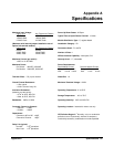
Specifications
Maximum Input Voltage:
High to Low
Any Terminal to Chassis
150VDC 150VDC
150VAC RMS 150VAC RMS
210VAC Peak 210VAC Peak
Power Up/Down States: All Open
Typical Time to Open/Close a Channel: 13 msec
Module Size/Device Type: C, register-based
(Maximum with internal jumpers installed or use of
Option 010 terminal module):
High to Low
Any Terminal to Chassis
60VDC 60VDC
30VAC RMS 30VAC RMS
42VAC Peak 42VAC RMS
Installation Category: IC 1
Connectors Used: P1 and P2
Number of Slots: 1
VXIbus Interface Capability: Interrupter, D16
Maximum Current (per switch):
1A DC or 1A AC RMS
Interrupt Level: 1-7, selectable
Maximum Power:
Per Switch: 40W DC, 40VA AC
Per Module: 320W DC, 320VA AC
Power Requirements:
Peak Module Current
Dynamic Module Current
Voltage: +5V +12V Voltage: +5V +12V
IPM: 0.10 A 0.24A IDM: 0.11A 0.01A
Thermal Offset: <70 µV per channel Watts/Slot: 1.0
Closed Channel Resistance:
>1.5Ω typical
>13.5Ω at end of relay life
Maximum Transient Voltage: 1300V
Insulation Resistance:
(between any two points):
>10
7
Ω at 40°C, 65% RH
>10
8
Ω at 25°C, 40% RH
Operating Temperature: 0° to 55°C
Storage Temperature: -40° to 75°C
Bandwidth: -3dB at 10 MHz Operating Humidity: 40°C and 95% RH
Crosstalk, Channel to Channel:
>100 kHz: >-70dB
>10 MHz: >-30dB
Operating Location: Intended for indoor use only.
Capacitance:
Common to NO or NC: >40pF
Channel to Channel: >30pF
IEC Pollution Degree 2
1
Normally, only non-conductive
pollution occurs. Occasionally, however, a temporary
conductivity caused by condensation must be expected.
Relay Life (typical):
No load: >10
6
operations
Max. load: >10
5
operations