


E1442A Application Examples 49Chapter 2
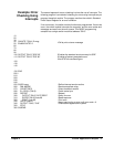
10 OUTPUT 722;"TRIG EXT;...."
! Configure instrument
20 OUTPUT 70915;"OUTP ON"
! Enable Trig Out port
30 OUTPUT 70915;"TRIG:SOUR BUS"
! GPIB bus triggering
40 OUTPUT 70915;"SCAN (@100:102)"
! Scan channels 00-02
50 OUTPUT 70915;"INIT"
! Enable scan.
60 FOR I=1 TO 3
! Start count loop
70 ENTER 722;A
! Enter reading
80 PRINT A
90 TRIGGER 70915
! Advance scan
100 NEXT I
! Increment count
110 END
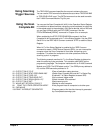
Example: Scanning
Using Trig Out and
Trig In Ports
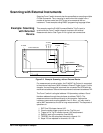
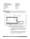
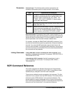
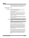
This example uses the E1406A Command Module Trig Out and Trig In
ports to synchronize Form C switch channel closures with an external
measurement device. See Figure 2-3 for typical user connections.
For this example, the mainframe and measurement instrument are
connected via GPIB with a mainframe at address 709 and the measurement
instrument at address 722. The Form C switch logical address is 120
(secondary address = 120/8 = 15 and therefore addressed through the
mainframe at 70915).
With this example, since synchronization with the computer cannot be
ensured, the external instrument must have internal memory capacity to
store the readings. Also, you must add the appropriate instrument
commands to line 10. The sequence of operation is:
Figure 2-3. Example: Scanning Using Trig Out and Trig In Ports
C
NC
NO
NO
NC
C
NC
NO
C
In
Trig
C
H
0
C
H
1
C
H
2
To DUTs
E1401 Mainframe
3458 Voltmeter
Out
Trig
HI
HI LO G
LO I
DUT
Common
Low
Ext Out
(VM Comp)
Ext Trig
E1406A
E1442A