


Getting Started 29Chapter 1
Example:
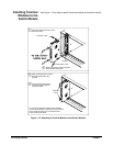
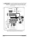
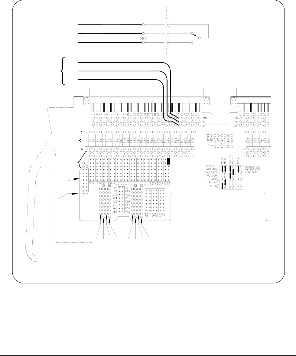
Straight-Through
Configuration
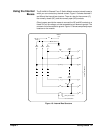
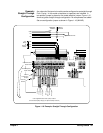
Any channel of the terminal module can be configured as a straight-through
Form C relay. In this mode no resistors or capacitors are included. A
two-position jumper is placed on the mode selection jumper. Figure 1-16
shows a typical straight-through configuration. No components are added.
Set one configuration jumper as shown in Figure 1-16 (INLINE).
Figure 1-16. Example: Straight-Through Configuration
TERMINAL
MODULE
SWITCH
MODULE
Channel 25
COM
NC
NO
Channel
Configuration
Jumpers
Number
Channel
User
Wiring
To
Terminal
Module
R
P
1
6
-
2
3
R
P
2
4
-
3
1
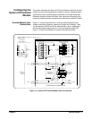
and associated pullup voltage (for optional standup resistors)
User Supplied Resistor Packs (SIP) Locations
V
2
4
-
3
1
V
1
6
-
2
3
R
P
8
-
1
5
V
0
-
7
V
8
-
1
5
R
P
0
-
7
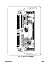
Channel Capacitor
Solder Holes
Channel Resistor
Solder Holes
NO
NC
COM
COM
NC