


E1442A Application Examples 43Chapter 2
Chapter 2
E1442A Application Examples
Using This Chapter
This chapter provides application information and examples for using the
E1442A 64-Channel Form C Switch Module in a switchbox. The chapter
contents are:
• General Scanning Information . . . . . . . . . . . . . . . . . . . . . . . . .41
• Saving and Recalling States. . . . . . . . . . . . . . . . . . . . . . . . . . .44
• Detecting Error Conditions . . . . . . . . . . . . . . . . . . . . . . . . . . . .44
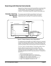
• Scanning with External Instruments . . . . . . . . . . . . . . . . . . . . .46
General Scanning Information
This section lists general scanning information for the E1442A module,
including:
• Switchbox Definition
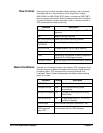
• How to Scan
• Reset Conditions
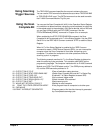
• Using Scanning Trigger Sources
• Using the Scan Complete Bit
Switchbox
Definition
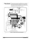
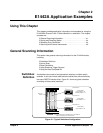
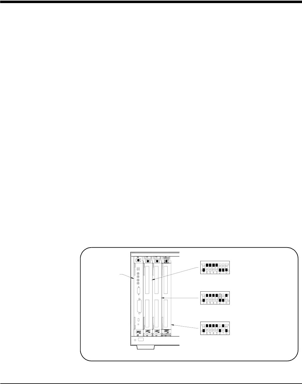
A switchbox can consist of a single-switch module or multiple-switch
modules. It can also include other switch modules that are controlled by
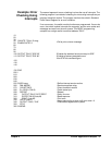
the same SWITCH device driver. Figure 2-1 shows a typical switchbox
consisting of three cards (modules).
Figure 2-1. Typical Switchbox Configuration
Command
Module
Note: Physical placement of the Module in the Logical Address
order is not required, but is recommended.
Switch Module
Logical Address = 120
Secondary Address = 15
Card Number 01
Logical Address = 121
Switch Module
Switch Module
Logical Address = 122
1
2
8
6
4
3
2
1
6
8
4
2
1
Card Number 02
6
4
1
2
8
1
6
3
2
8
4
1
2
Card Number 03
6
4
1
2
8
1
6
3
2
8
4
1
2