


14 Getting Started Chapter 1
Terminal Module
Descriptions
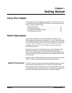
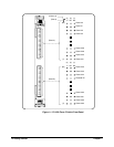
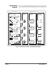
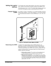
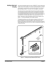
Figure 1-3 shows the Standard Terminal Module Form C configuration with
solder lugs, the Option 010 Terminal Module Form C configuration with
signal conditioning circuitry, and the Option 020 Form A Screw Terminal
configuration.
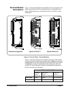
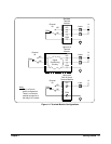
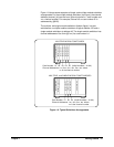
Figure 1-4 shows the three terminal modules and options for NO and NC
connections for each terminal type. A switch (relay) is open when contact is
made between the normally closed (NC) contact and common (C). A switch
is closed when contact is made between the normally open (NO) and
common (C). Any combination of open or closed states is allowed at one
time for all channels on the module.
Figure 1-3. Form C Switch - Terminal Modules
Standard Configuration
Option 010 Form C
Option 020 Form A
Terminal Module Type
Standard
Form C
Solder Lug
Option 010
Form C
Signal Conditioning
Option 020
Form A
Screw Terminal
Relay Open Load 1 Load 1 No Connection
Relay Closed Load 2 Load 2 Load 2