


18 Getting Started Chapter 1
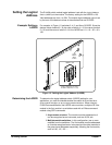
Setting the Logical
Address
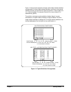
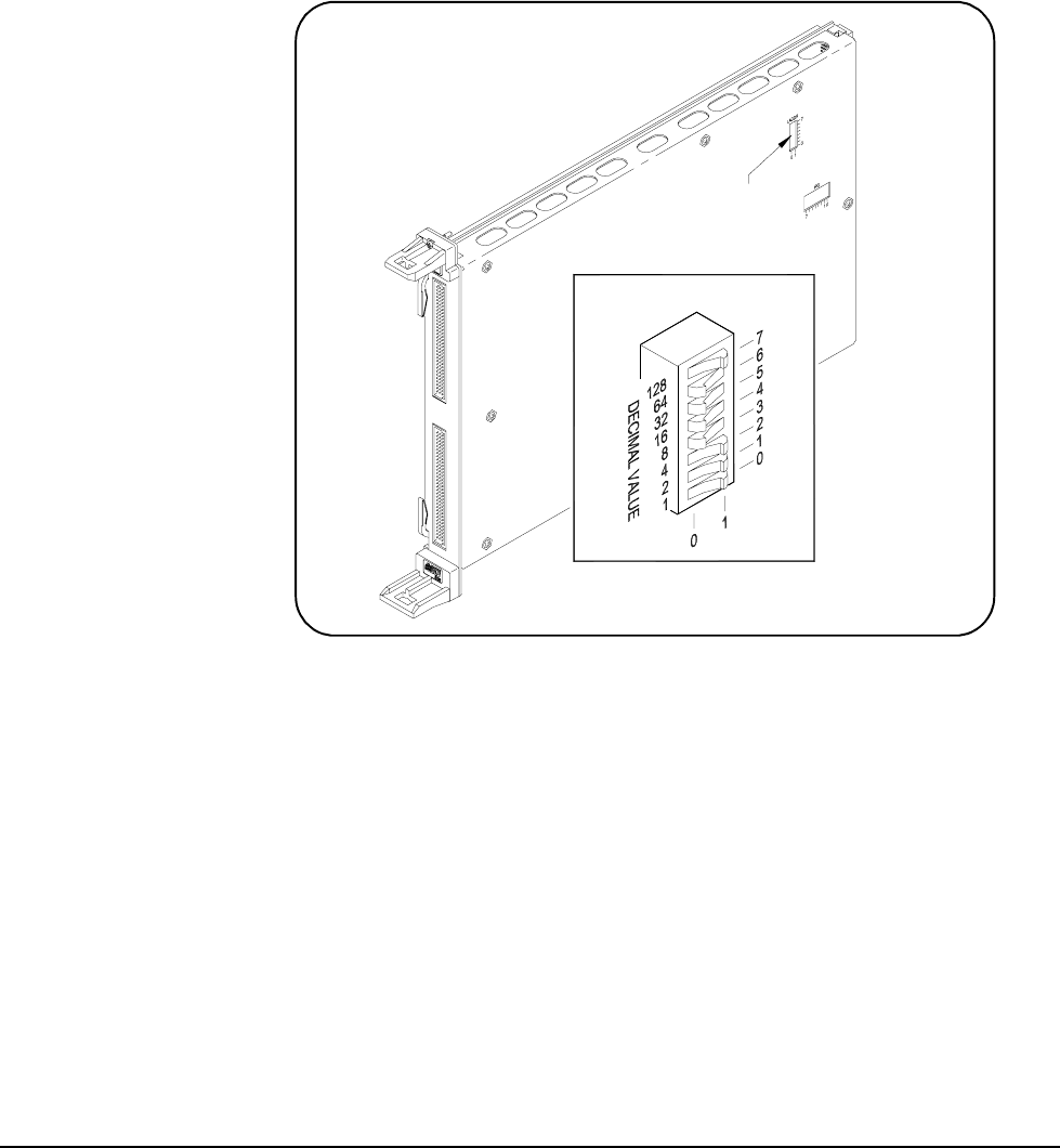
The E1442A switch module logical address is set with the Logical Address
Switch (LADDR)
on the module. The factory setting for the LADDR is 120.
Valid addresses are from 1 to 254. The module logical address value is set
by the sum of the decimal values of the switches that are CLOSED.
Example: Setting a
LADDR
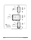
For example, in Figure 1-5, switches 3, 4, 5, and 6 are CLOSED. Since the
decimal value of switch 3 = 8, the value of switch 4 = 16, the value of switch
5 = 32, and the value of switch 6 = 64, the LADDR set = 8 + 16 + 32 + 64 =
120.
Determining the LADDR To determine the logical address switch (LADDR) setting for your
application, you must first decide whether the switch is to be used as a
single-module switchbox or as a multiple-module switchbox. When using an
E1406 Command Module, the LADDR value must be a multiple of 8 if the
module is the first module in a switchbox used with a VXIbus command
module using SCPI commands.
• Single-module switchbox. The module must be addressed so it
can be recognized as an instrument, such as 48, 56, etc..
• Multiple-module switchbox. In this configuration, two or more
modules form the switchbox. The first module must be addressed
so it can be recognized as an instrument and the other modules in
the group have addresses sequentially following the first module,
such as 120, 121, 122 ....
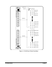
Figure 1-5. Setting the Logical Address (LADDR)
OPEN = Switch Set To 0 (OFF)
CLOSED = Switch Set To 1 (On)
LADDR = 120
Location
Switch
Address
Logical