


92 Register-Based Programming Appendix B
If bit 6 is returned as a 0, interrupts are enabled. If bit 6 is returned as a 1,
interrupts are disabled.
Bit 14 is the MODID bit. When a 0 is returned in bit 14, the module has been
selected with a high state on the P2 MODID line (this occurs during turn-on).
If a 1 is returned, the module has not been selected.
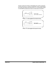
Switch Enable Register A read of any of the Switch Enable Registers always returns FFFF
16
,
regardless of the channel states.
Writing to E1442A
Registers
You can write to the following Form C switch registers:
• Status/Control Register (base + 04
16
)
• Switch Enable Register for channels 0 - 15 (base + 10
16
)
• Switch Enable Register for channels 16 - 31 (base + 12
16
)
• Switch Enable Register for channels 32 - 47 (base + 14
16
)
• Switch Enable Register for channels 48 - 63 (base + 16
16
)
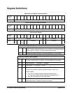
Status/Control Register Writing a 1 to bit 0 of the Status/Control Register (base + 04
16
) to reset the
switch module (all channels open). Resetting the module enables interrupts.
NOTE It is necessary to write a 0 to bit 0 after the reset has been performed
before any other commands can be programmed and executed.
To disable the interrupt generated when channels are opened/closed, write
a 1 to bit 6 of the Status/Control Register.
NOTE Typically, interrupts are disabled when doing register-level access to a
module. Refer to the operating manual of the command module or the
embedded controller being used to handle interrupts. Interrupts are
re-enabled after a reset.
Bit 12 provides status on fuse F4. This is a user-installed component
required to provide the +5V pullup voltage to the module’s internal bus for
the NC and NO contacts. A 0 indicates the fuse is not installed (or the fuse
is blown if installed). A 1 indicates you previously installed the fuse and it is
good.
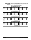
Switch Enable Registers Writes to the Switch Enable Registers (base + 10
16
through base + 16
16
)
enable you to open or close the desired channel. For example, write a 1 to
bit 2 of the Switch Enable Register (base + 10
16
) to close channel 02. Or,
write a 0 to bit 15 of the register at base + 16
16
to open channel 63.
NOTE All relays are non-latching and will open during a power-down.