


34 Getting Started Chapter 1
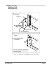
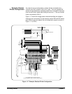
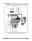
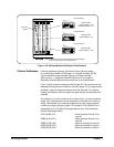
Example: Normally Open
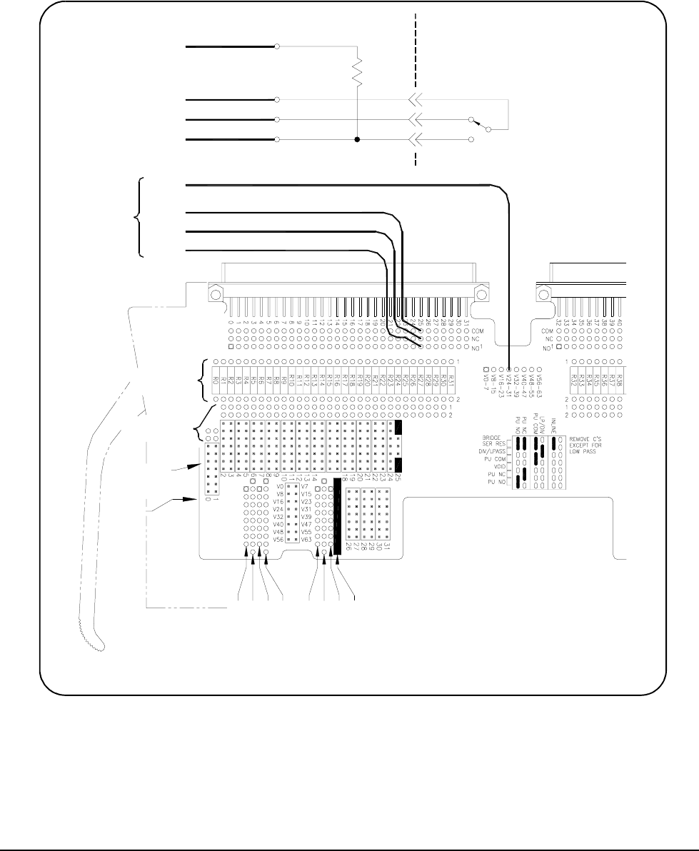
Terminal Pullup
Configuration
Any channel can be configured as a pullup (or pulldown) resistor connected
to any of the contacts of the Form C relay. Figure 1-21 shows channel 25
with the pullup attached to the NO contact. For this example, SIP resistor
pack RP24-31 is to be added. Set two configuration jumpers as shown in
Figure 1-21 (PU NO).
Figure 1-21. Example: Normally Open Terminal Pullup Configuration
TERMINAL
MODULE
SWITCH
MODULE
Channel 25
V24-31
RP
Channel
Configuration
Jumpers
Number
Channel
COM
NC
NO
User
Wiring
To
Terminal
Module
Vpullup
Pullup
Voltage
24-31
R
P
1
6
-
2
3
R
P
2
4
-
3
1
and associated pullup voltage (for optional standup resistors)
User Supplied Resistor Packs (SIP) Locations
V
2
4
-
3
1
V
1
6
-
2
3
R
P
8
-
1
5
V
0
-
7
V
8
-
1
5
R
P
0
-
7
COM
NC
NO
COM
NC
NO
Channel Capacitor
Solder Holes
Channel Resistor
Solder Holes