


24 Getting Started Chapter 1
Configuring the Terminal Modules
This section gives guidelines to configure the Standard Form C
Configuration, Option 010 Form C Configuration, and the Option 020 Form
A Configuration terminal modules, including:
• Wiring the Terminal Modules
• Attaching Terminal Modules to the Switch Module
• Configuring the Option 010 Terminal Module
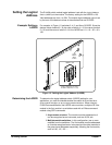
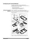
Wiring the Terminal
Modules
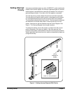
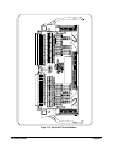
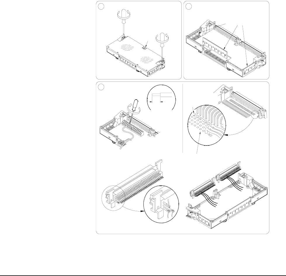
Figure 1-11 and Figure 1-12 show steps to wire terminal module s.
Maximum terminal wire size is No. 16 AWG. Wire ends should be stripped
5mm (0.2 in.) and tinned. When wiring all channels, use a smaller gauge
wire (No. 20-22 AWG).
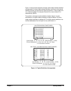
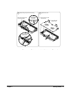
Figure 1-11. Wiring the Terminal Modules (cont’d on Figure 1-12)
on terminal module.
Then install connectors
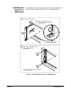
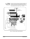
STANDARD TERMINAL MODULE
Solder-Lug.
Solder wires to
See Figure 1-1
NO pin-out from the switch
for Channel COM, NC and
module.
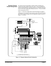
TERMINAL MODULE
OPTION 020
Attach wires.
Remove clear cover.
Tighten screw.
Insert wire into terminal.
3
1
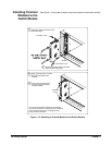
Flammability Rating
Use wire size 16-26
AWG with VW1
0.2"
5mm
Tab
A. Release screws.
B. Press tab forward
and release.
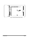
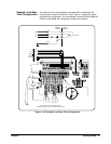
Solder field wiring directly
NOTE: Solder eyes will accept a dual 96-pin DIN-C
OPTION 010 TERMINAL MODULE
connector.
to solder eyes.
Remove 1 of the 3
wire exit panels.
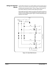
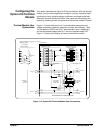
Number
Channel
Remove and retain wiring exit panel.2