


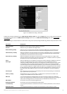
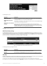

Figure 6- 115.OSPF Interface Settings – Edit window
Configure each IP interface individually using the O
SPF Interface Settings – Edit menu.Click the Apply button when you have entered the settings.The
new configuration appears listed in the
OSPF Interface Settings table.To return to the OSPF Interface Settings table,click the Show All OSPF
Interface Entries link.
OSPF interface settings are described below.Some OSPF interface settings require previously configured OSPF settings.Read the descriptions below for details.
Parameter Description
Interface Name Displays the of an IP interface previously configured on the Switch.
Area ID Allows the entry of an OSPF Area ID configured above.
Router Priority (0-255) Allows the entry of a number between 0 and 255 representing the OSPF priority of the selected area.If a
Router Priority of 0 is selected,the Switch cannot be elected as the Designated Router for the network.
Hello Interval (1-65535) Allows the specification of the interval between the transmission of OSPF Hello packets,in seconds.Between 1
and 65535 seconds can be specified.The Hello Interval,Dead Interval,Authorization Type,and Authorization
Key should be the same for all routers on the same network.
Dead Interval (1-65535) Allows the specification of the length of time between the receipt of Hello packets from a neighbor router
bef
or
e the selected ar
ea declares that router down.An interval between 1 and 65535 seconds can be specified.
The Dead Interval must be evenly divisible by the Hello Interval.
State Allows the OSPF interface to be disabled for the selected area without changing the configuration for that area.
Auth Type This field can be toggled between None, Simple, and MD5 using the space bar.This allows a choice of
authorization schemes f
or OSPF pack
ets that ma
y be exchanged o
v
er the OSPF r
outing domain.None specifies
no authorization.Simple uses a simple password to determine if the packets are from an authorized OSPF
router.When Simple is selected,the Auth Key field allows the entry of a 8 character password that must be the
same as a password configured on a neighbor OSPF router.MD5 uses a cryptographic key entered in the MD5
Key Table Configuration menu.When MD5 is selected,the Auth Key ID field allows the specification of the Key
ID as defined in the MD5 configuration above.This must be the same MD5 Key as used by the neighboring
router.
A
uth. Key ID
Enter a K
ey ID of up to 5 characters to set the Auth.Key ID for either the Simple Auth Type or the MD5 Auth
Type,as specified in the previous parameter.
Metric (1-65535) This field allows the entry of a number between 1 and 65,535 that is representative of the OSPF cost of
r
eaching the selected OSPF interface
.The default metric is 1.
DR State A read only field describing the Designated Router state of the IP interface.This field many read DR if the
interface is the designated router, or Backup DR if the interface is the Backup Designated Router.The highest IP
address will be the Designated Router and is determined by the OSPF Hello Protocol of the Switch.
DR Address The IP ad
dress of the aforementioned Designated Router.
Backup DR Address The IP address of the aforementioned Backup Designated Router.
Transmit Delay A read only field that denotes the estimated time to transmit a Link State Update Packet over this interface, in
seconds.
Retransmit Time A r
ead onl
y field that denotes the time betw
een LSA r
etransmissions over this interface,in seconds.
119
Allied Telesyn AT-9724TS High-Density Layer 3 Stackable Gigabit Ethernet Switch